Kerb and Edging Details for External Works
How kerb and edging details work in external works drawings, and how real paving blocks fit alongside them in a site plan.
Saumyajit MaityUpdated 27 July 202610 min read

External works is its own drawing category, and it's easy to underrate
So much attention in a typical drawing set goes to the building itself that the site around it, the paths, the parking, the planted edges, the kerb lines separating one surface from another, ends up drawn almost as an afterthought, a few hatched areas with a label. On a real project that's a mistake, because external works has its own detailing challenges, drainage falls, surface transitions, edge restraint, that are every bit as specific as anything inside the building, and a kerb or edging detail is exactly the drawing that resolves one of the most common of those junctions: where one paved or planted surface stops and another starts.
At the end of the day a kerb is doing a structural and a drainage job at once, restraining the paving or the planting bed on one side so it doesn't spread or erode, and usually managing a change in level or a drainage fall between two surfaces, a raised path edge next to a lawn, or a channel kerb directing surface water toward a drain.
It's worth being honest about why this category of drawing gets underrated so often too. A building's walls and openings are what a client walks through and lives with every day, so they naturally get the most design attention, while the site around the building is treated as the space left over once the building footprint is settled. But poorly detailed external works shows up fast and visibly, a paving edge that's crept sideways within a year, a kerb that's cracked from vehicle overrun it was never detailed to resist, a planting bed edging that's rotted or rusted through, so the actual cost of underrating this drawing category tends to land within the first year or two of a building's life, not decades down the line the way some structural issues might.
What a kerb detail actually shows
A kerb detail is a section, drawn at a reasonably large scale (often 1:10 or 1:20), cut across the kerb line, and it typically shows the kerb unit itself (precast concrete, natural stone, or a poured-in-place concrete edge, each drawn with its own hatch and profile), the bedding material it sits on (usually a concrete haunch or bedding mortar), and how it transitions to the surfaces on either side, a paving course on one side and topsoil or a planting bed on the other, for instance.
The things worth checking specifically on a kerb detail: the exposed height of the kerb above the adjacent lower surface (which determines whether it reads as a real edge restraint or barely registers), the fall or slope built into the paving surface running toward or away from the kerb line (critical for surface water management), and whether the kerb is bedded on a proper haunch rather than just sitting loose on the sub-base, because an unhaunched kerb is one of the most common on-site failures in external works, it shifts and cracks within a season or two of any vehicle or foot traffic near it.
Drainage detailing at the kerb line deserves its own bit of attention, because a kerb is very often the thing actually directing surface water rather than just sitting beside it decoratively. A simple upstand kerb just restrains the edge and lets water sheet across the paved surface toward a separate drainage point elsewhere. A channel or dish kerb, by contrast, is shaped specifically to collect water running off the adjacent surface and carry it along the kerb line toward a gully or a linear drainage channel, which changes the kerb's cross-section profile substantially, it's shaped like a shallow trough rather than a simple upright block. Reading which type a detail is showing you, upstand or channel, tells you immediately whether that kerb line is doing passive edge restraint or active water management, and mixing the two up when specifying leads to water pooling somewhere it was never meant to collect.
Edging: the lighter-weight cousin of a full kerb
Edging serves a similar purpose to a kerb but at a lighter scale, usually restraining a planting bed, a gravel path, or a smaller paved area where full kerb-and-channel drainage detailing isn't needed. Typical edging materials include timber boards, steel or aluminium edge strips, brick-on-edge courses, or smaller precast concrete edging units, and the detail for any of these is simpler than a full kerb section, mostly concerned with how deep the edging is set into the ground and how it's fixed or pinned in place so it doesn't creep sideways under the pressure of the material it's holding back.
The practical difference worth remembering when you're choosing which to specify: a kerb is a structural, load-bearing edge restraint that often manages drainage too, while edging is a lighter containment feature mostly concerned with keeping loose material, gravel, mulch, soil, in place along a boundary. Mixing the two up on a drawing (calling for a slim timber edge where the site actually needs a proper trafficked kerb, for example) is a genuine and fairly common specification error.
Material choice for edging is worth a closer look too, because each option carries a genuinely different maintenance and lifespan trade-off rather than being purely a cosmetic choice. Timber edging is inexpensive and easy to cut to curves but will eventually rot or warp, especially in constant ground contact, and needs treating or periodic replacement. Steel or aluminium strip edging holds a crisp, thin line particularly well against gravel or loose mulch and lasts far longer, but costs more and is less forgiving to adjust once installed. Brick-on-edge and precast concrete edging units sit closer to a mini-kerb in behaviour, more permanent, more expensive, and better suited to a defined, formal edge than a casual garden bed boundary. None of these choices changes the basic principle behind the detail, enough of the unit buried to resist lateral pressure with a small consistent reveal above the finished surface, but the material does change how that principle gets drawn and specified.
Where paving blocks fit into this picture
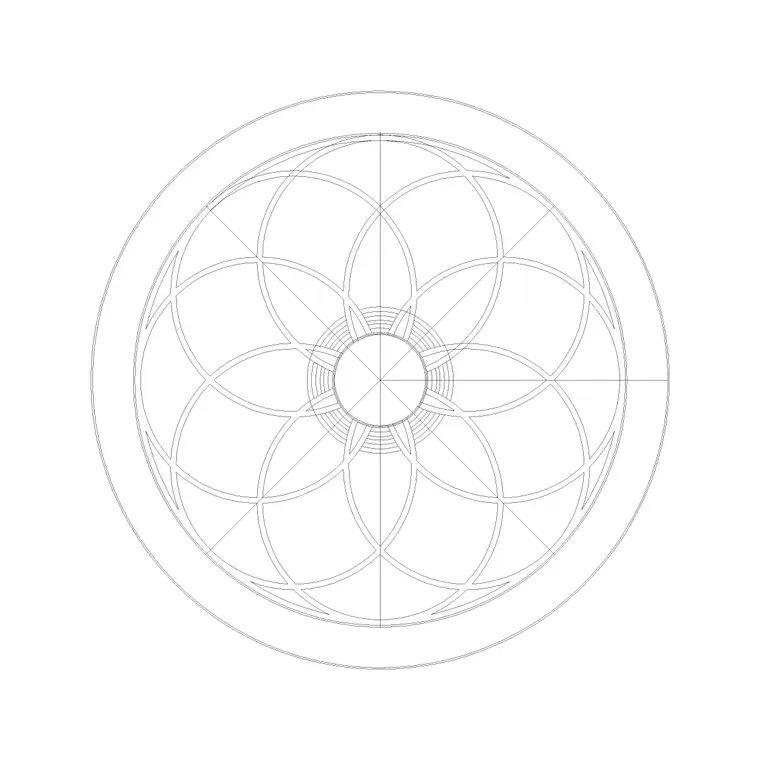
Our paving category carries 83 real downloadable products, Paving Block 1 through numbered variants well into the 30s and beyond, all plan-view hatching and unit patterns representing different paving layouts and module sizes. These are exactly the blocks you'd use to fill the paved area sitting inside the kerb or edging line on a site plan, giving you the surface pattern and module coordination for the hardscape itself.
What a paving block on its own doesn't show, honestly, is the edge condition, the kerb or edging detail is a separate drawing, usually a section rather than a plan, that resolves how that paving pattern actually terminates and transitions at its boundary. So a complete site plan realistically layers a paving block like Paving Block 1 for the surface pattern, with a kerb or edging line drawn around its perimeter, and then a large-scale section detail produced separately for the specific kerb or edging condition used on that project. None of our paving blocks are drawn to double as that edge detail, treat them as the fill pattern and the edge as its own drawing.
With 83 numbered paving blocks to choose from, one practical habit worth building is picking a module size and pattern that actually suits the scale of the paved area before worrying about the edge condition around it. A small, tight unit pattern reads as busy and can look cluttered across a large open plaza, while an oversized module can look clumsy in a narrow path barely wider than the units themselves, so it's worth laying a few candidate paving blocks over your actual site plan at true scale before committing, rather than picking one that just looks good in isolation.
Typical dimensions worth knowing
Kerb heights on external works vary a fair amount depending on whether it's a pedestrian path edge or a vehicular kerb doing real traffic restraint work, but a light pedestrian kerb typically sits somewhere in a modest range above the adjacent surface, just enough to be visually and physically distinct, while a full vehicular kerb needs to stand taller and be bedded far more robustly to survive wheel loads and occasional mounting. Rather than quoting a single fixed number here, the honest guidance is that kerb height and bedding depth are governed by the specific loading condition and local specification for the project, so always confirm against the relevant local standard rather than a general figure.
Edging depth (how far it's set into the ground) is similarly project-specific, but the general principle holds across materials, enough of the edging unit needs to be buried to resist the lateral pressure of whatever it's restraining, with only a small consistent reveal showing above the finished surface on the contained side.
Dropped kerbs and accessible transitions
One specific kerb condition worth understanding on its own is the dropped kerb, sometimes called a flush kerb, used anywhere a path or driveway needs to transition smoothly across what would otherwise be a raised kerb line, a pedestrian crossing point, a driveway entrance, or a step-free route between a car park and a building entrance. Instead of the kerb standing proud of the adjacent surface at full height, it tapers or drops down to near-flush over a short run, and the detail for this transition needs to show that taper clearly, along with how drainage still works across a section of kerb that's no longer doing its usual job of holding back water at full height.
This is another point where the same underlying principle from the door threshold post in this series shows up again in a different context, wherever step-free, level access matters, the standard detail (a raised kerb, a raised sill) has to be deliberately modified, and that modification has to be drawn and specified explicitly rather than assumed. A dropped kerb detail that forgets to resolve drainage across the flush section is a common oversight, water that used to be stopped by the raised kerb now has somewhere new to go, and if that hasn't been thought through the flush crossing point becomes the lowest point on the site and collects standing water exactly where people are meant to walk or drive across it.
Common mistakes on kerb and edging details
A handful of issues that come up repeatedly on external works drawings:
- No haunch or bedding shown under a kerb, leaving it structurally unsupported on paper even if it's implied on site - Surface fall not indicated, so it's unclear which way water is meant to drain relative to the kerb line - Edging specified where the loading condition actually calls for a full structural kerb, or vice versa, over-specifying where a lighter edge would do - Paving pattern block used in the plan without any edge treatment drawn at all around its perimeter, leaving the boundary condition completely undefined - Level mismatch between the kerb detail and the finished floor levels shown elsewhere in the drawing set, especially at a building threshold where external works meets an entrance
Putting it together on a site plan
For instance, on a small courtyard or entrance path project, a realistic drawing set would place several paving blocks from our library, Paving Block 1 and a few of its numbered siblings, to build up the actual surface pattern across the site plan, with a kerb or edging line drawn around the boundary of that paved zone, and a separate large-scale section detail produced for whichever kerb or edging condition the project specifies. The paving block gives you the surface, the site plan gives you the layout, and the kerb or edging detail gives the site team the buildable edge condition, three different drawings doing three different jobs, the same layered logic that runs through every construction detail covered in this series.
External works is easy to leave until last on a project, and it's exactly the wrong instinct, because the edge condition between a paved surface and whatever sits next to it is where water management, structural restraint and long-term durability all come together in a fairly small strip of drawing. Give the kerb or edging line the same attention you'd give a door threshold or a window sill, and the paving pattern sitting inside it will actually hold up the way it's meant to.
Further reading
Questions
Frequently asked
What's the difference between a kerb and edging in external works?+
A kerb is a structural, often load-bearing edge restraint that frequently manages drainage as well, typically used along paths and vehicular surfaces. Edging is a lighter containment feature, mostly holding back loose material like gravel or soil along a boundary, without the same structural or trafficked loading requirement.
Do you have downloadable kerb or edging construction details?+
We carry 83 real paving blocks, like Paving Block 1 and its numbered variants, useful for the surface pattern inside a paved area. A large-scale kerb or edging section detail is a separate drawing type produced specifically for the project's edge condition, not something a paving pattern block is drawn to include.
Why does a kerb need a haunch underneath it?+
A haunch, usually a concrete bedding shoulder, keeps the kerb unit from shifting or cracking under vehicle or foot traffic. An unhaunched kerb is one of the more common external works failures, working loose within a season or two.
How tall should a kerb be?+
It depends heavily on whether it's a pedestrian edge or carrying real vehicular loading, so there is no single universal figure. Always confirm kerb height and bedding depth against the relevant local specification or standard for the project rather than a general guideline.
Free downloads from this article




Free CAD block library
Download the blocks from this article — free, no signup