Window Sill and Head Detail Drawings Explained
What a window sill and head detail actually shows beyond the plan symbol, explained with real window blocks you can reference.
Saumyajit MaityUpdated 14 May 202610 min read
The window plan symbol is only the top-down half of the story
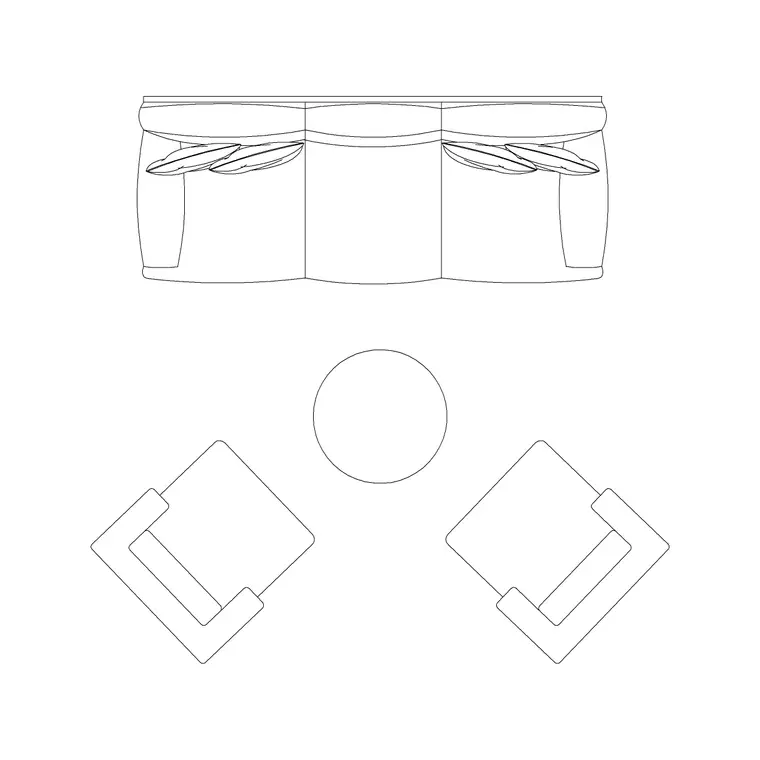
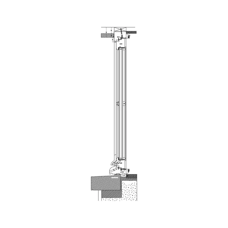
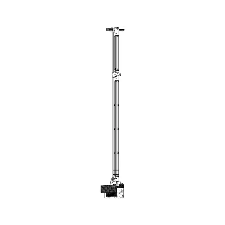
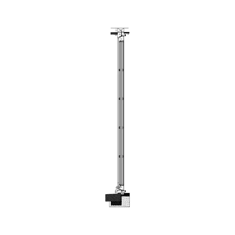
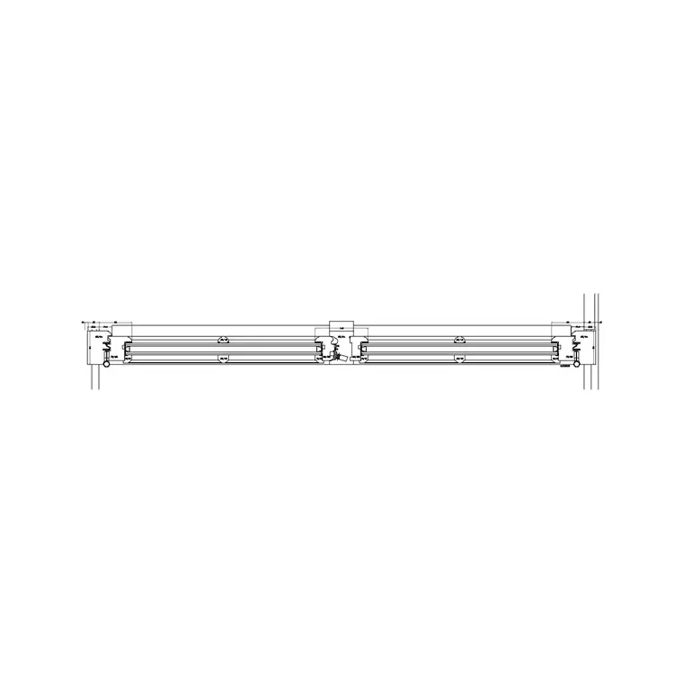
Open any window block on this site and what you get is a plan (looking down through the wall) and usually an elevation (looking straight at it from outside), and between those two views you can already tell the overall width, the number of shutters or sashes, and roughly how it opens. That covers what most floor plans and elevations need. What it doesn't cover, and what a sill and head detail is drawn specifically to show, is the vertical section through the opening, cut top to bottom, revealing how the window frame actually sits inside the wall thickness at the bottom (the sill) and the top (the head), plus the jambs running up each side.
So basically you've got three drawing types working together on any real project: the plan for horizontal coordination, the elevation for what it looks like from outside, and the section detail for how it's actually built. Skipping the third one and assuming the plan and elevation are enough is a common shortcut on quick student drawings, but it's not something a real construction set can get away with, because none of the waterproofing, insulation or fixing information lives in a plan or elevation view.
And for instance, the same opening will show up differently across all three drawings and that's exactly the point rather than a flaw, the plan shows you the frame width and how far it recesses into the wall thickness, the elevation shows you the glazing pattern and shutter or sash arrangement as seen from the room or the street, and the section shows you the actual vertical build-up, sill upstand, frame depth, head bearing, that neither of the other two views is drawn to carry. Treat all three as one coordinated set describing a single opening rather than three unrelated drawings that happen to share a title block.
The sill: the part doing the water-management work
The sill is the horizontal member at the bottom of the opening, and on an external wall it's arguably the single most failure-prone junction in the whole window assembly, because it's the point water collects and has to be shed away from the building rather than into it. A proper sill detail shows a slope on the top face (falling away from the glass line toward the outside), a drip groove or throat on the underside so water doesn't track back and run down the wall face beneath it, and usually a small upstand at the inside edge where the frame sits, so any water that does get past the seal has somewhere to go other than into the room.
Material matters a lot here too. Precast concrete sills, natural stone, tile and rendered brick-on-edge sills all get drawn with different hatch conventions and different thicknesses, and the detail needs to show how the sill material actually meets the wall finish above and below it, often with a separate flashing or damp-proof membrane tucked in behind. If you're checking rather than drawing one of these, the first thing worth confirming is that the slope and drip groove are actually shown, because a flat sill with no throat is a leak waiting to happen no matter how good the rest of the detail looks.
The sill also has to resolve against whatever's happening on the wall below it, and this is where cavity wall construction specifically adds a step most beginners miss the first time they draw one. Where a window sits in a cavity wall, a small stepped flashing, often called a cavity tray, has to be built in below the sill to catch any water that gets into the cavity and direct it back out through weep holes in the outer leaf, rather than letting it track down inside the wall and show up as a damp patch somewhere well below the window months later. It's a detail that's completely invisible once the wall is finished and rendered, which is exactly why getting it right on the drawing, and confirming it was actually built that way on site, matters more than most other parts of the section.
The head and jambs: framing and structural support above the opening
The head is the top of the opening, and unlike the sill its main job is structural rather than waterproofing, because it has to support whatever wall is sitting above the window, usually via a lintel spanning across the opening. In the detail you'll see the lintel drawn as a distinct element, concrete, steel or timber depending on construction type, bearing onto the wall on each side of the opening by a defined length, with the window frame head fixed underneath it and a small gap (often filled with a compressible sealant or a cavity closer) to allow for minor structural movement without cracking the frame or the wall finish.
The jambs, the vertical sides of the opening, connect the sill to the head and in the detail show the frame fixed to the surrounding wall with packers or frame ties, insulation filling any residual cavity, and internal and external trims closing off the junction. As with a door jamb, the width of the rebate in the jamb detail has to match the frame thickness shown in the plan, and it's a genuinely common coordination error for those two drawings to disagree slightly when they're produced by different people or updated at different times.
Lintel bearing length specifically is worth understanding even at a basic level, because it's the number most often left off a quick sketch detail. A lintel doesn't just sit on top of the opening, it extends past each side of the opening onto solid wall so the load actually transfers down into the structure below rather than concentrating right at the edge of the opening, and how far it needs to extend depends on the span and the loading, which is exactly the kind of number a structural engineer specifies for the project rather than something read off a general guide. What a beginner reading a section can usefully check, without needing to be a structural engineer, is simply whether a bearing length is shown and dimensioned at all, a lintel drawn flush with the opening edges and no bearing called out is an incomplete detail regardless of what the actual number should be.
What our window blocks actually show, and what to add on top
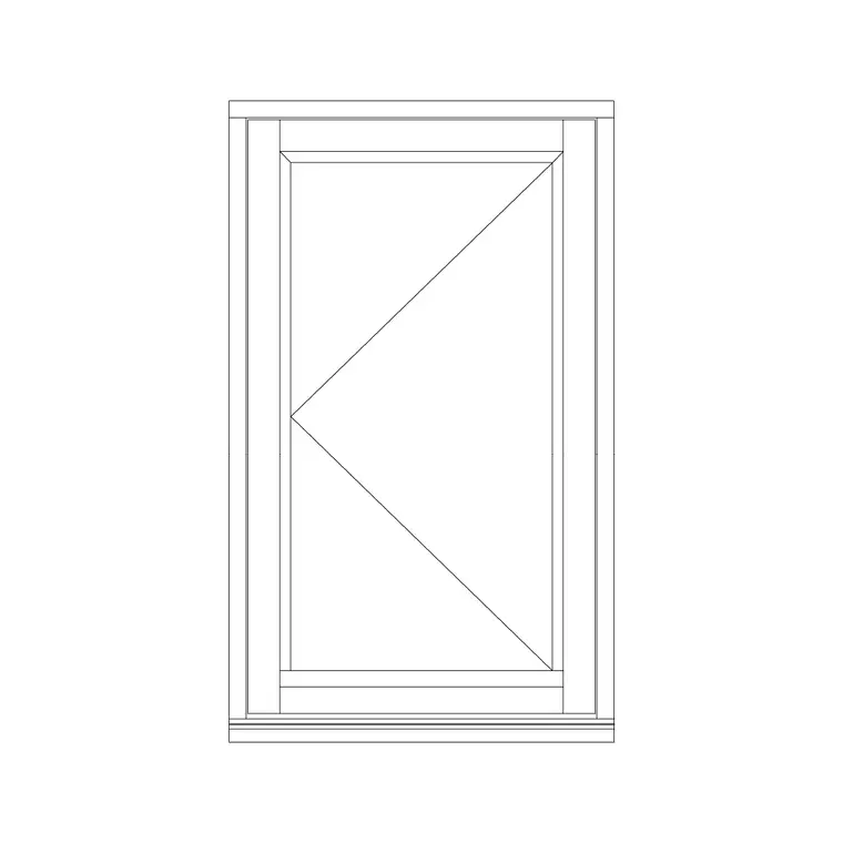
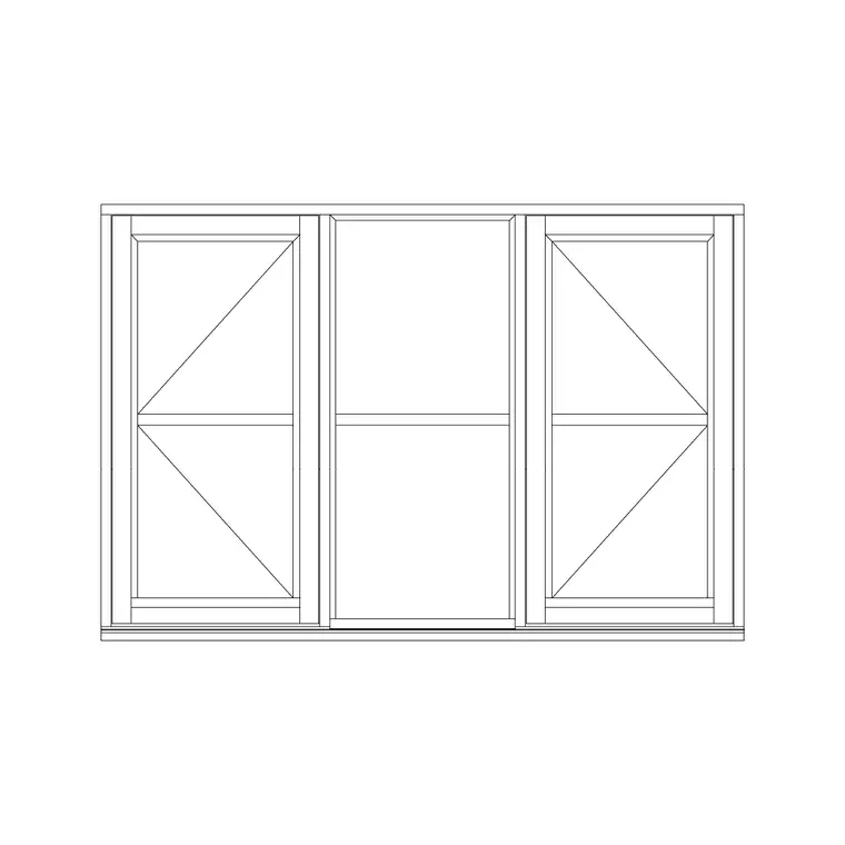
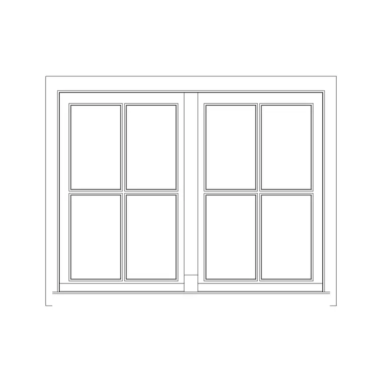
Our windows category holds 27 real downloadable products, plan and elevation pairs like Window Plan (1) through Window Plan (4), roman-style windows, single and double shutter openable types and sliding variants. Opening Window Plan (1) alongside its elevation view gives you the overall frame width, mullion spacing and shutter arrangement clearly, which is exactly the information a floor plan or a basic elevation drawing needs.
What none of those plan-scale blocks show, honestly, is the vertical sill and head section, because that's a different drawing type at a different scale, typically 1:5 or 1:10 rather than the 1:50 or 1:100 a floor plan usually sits at. The sensible workflow is to use the window plan block to place and size the opening correctly across your floor plan, and then build or source the separate large-scale sill and head detail for the actual construction documentation, exactly the same relationship as a door plan block and its own frame detail.
Worth calling out specifically is that the opening style itself changes what the sill and head detail even needs to resolve. A sliding window, like Single Shutter Sliding Window, needs a track detail at the sill rather than a simple fixed rebate, because the sash has to run horizontally along a guide rather than swinging on hinges. A roman-style arched window, like Roman Window 2 Shutter or Square Roman Windows, changes the head detail entirely, because the top of the opening is curved or has a distinct upper profile rather than a straight lintel line, which affects how the frame is cut and how the head bearing is resolved around that curve. And Patio Sliding Door Plan and Patio Sliding Door Elevation, which sit in our windows category despite functioning more like a full-height sliding door, need a threshold detail closer to the door threshold post in this series than a typical raised window sill, precisely because people actually step through the opening rather than just looking through it. None of these are interchangeable details, so matching the plan block's opening type to the correct sill and head detail for that type is worth double-checking every time.
Typical window sizes worth knowing before you detail one
There's no single universal standard window size the way there is for a sheet of paper, window sizes get set by the building's proportions, the room's daylighting needs and local building regulations, but there are some broadly typical ranges worth knowing. Domestic window widths commonly land somewhere in the 600mm to 1800mm range for a single unit, with height varying more depending on sill height off the finished floor (often around 900mm to 1000mm in a habitable room, lower in a kitchen or bathroom, and down near floor level for a full-height opening).
Because those numbers vary so much by project and by local code, treat them as typically-observed ranges rather than a rule, and always check the governing building regulations for the specific project rather than assuming a size from a general guide like this one is compliant.
Sill height off the finished floor is worth a second look too, since it changes for reasons beyond just style preference. A kitchen window sill often sits noticeably lower than a living room window so it clears a worktop rather than a wall, a bathroom window sometimes sits higher for privacy, and anywhere a window doubles as an emergency escape route in a bedroom, sill height and clear opening size both get checked against specific safety requirements rather than general comfort. None of that changes how the sill and head detail is drawn structurally, the slope, the drip groove, the lintel, but it does change where that whole assembly sits vertically within the wall section, which is worth confirming against the room's actual furniture layout and use before finalising a height.
Common mistakes in sill and head details
The recurring issues worth watching for, whether you're drawing the detail yourself or checking one someone else produced:
- Sill drawn flat with no slope or drip groove, which is a direct water-ingress risk - Lintel bearing length not shown or too short for the loads it's carrying - Frame rebate in the jamb detail not matching the frame width shown in the window plan - Missing insulation or cavity closer at the jamb, leaving a thermal bridge straight through the wall - Internal sill (the board or trim on the room side) not accounted for, leaving an awkward unfinished junction at the bottom of the opening
A quieter but still common mistake is treating the sill and head detail as a one-off, drawn once and reused unchanged across every window on a project regardless of orientation or exposure. A window on a sheltered, south-facing wall and a window on an exposed, weather-facing gable genuinely don't need identical waterproofing detailing, and assuming one detail fits every opening on the elevation is a shortcut that tends to show up as a leak on exactly the wall that needed the extra attention.
Putting the plan, elevation and detail together
For instance, if you're documenting a small residential extension, a realistic package would have the window plan block placed correctly on the floor plan (from our library, something like Window Plan (2) or one of the single-shutter openable types depending on the opening style), the same window drawn in elevation to show glazing bar arrangement, and then a large-scale sill and head section detail produced separately to carry the waterproofing and structural information the plan and elevation can't show. None of our plan-view window blocks are drawn to double as that section detail, and treating them as if they were is the single most common misunderstanding around window construction drawings, so keep the two drawing types doing separate jobs and cross-check them against each other rather than substituting one for the other.
That same relationship, plan-level reference geometry alongside a project-specific large-scale section, is the pattern worth carrying into every other junction in a building, the door threshold covered elsewhere in this series, the staircase going and riser, the kerb line at the edge of a paved area. Once you've internalised it on a window, it stops feeling like a special case and starts feeling like the normal, expected way any two building elements meet.
Further reading
Questions
Frequently asked
What's the difference between a window plan and a window sill detail?+
The plan shows the opening width and shutter arrangement at a small scale for floor plan coordination. The sill and head detail is a separate large-scale section (often 1:5 or 1:10) that shows the actual sill slope, drip groove, lintel and frame fixings at the top and bottom of the opening.
Do you have downloadable window sill detail drawings?+
We have 27 real window plan and elevation blocks, including Window Plan (1) through Window Plan (4) and several shutter and sliding types. These show the opening in plan and elevation; a full large-scale sill and head section is a separate detail drawing you would produce alongside them.
Why does a window sill need a drip groove?+
Without a groove cut into the underside of the sill, rainwater running off the sloped top face can travel back underneath the sill by capillary action and run down the wall face beneath the window, staining or damaging the finish over time.
How wide is a typical residential window?+
Widths typically range somewhere around 600mm to 1800mm for a single unit, though the exact size depends on the room, the daylighting requirement and the local building code, so always confirm against project-specific regulations rather than a general range.
Free downloads from this article
Free CAD block library
Download the blocks from this article — free, no signup