How to Read a Wall Section Drawing: A Beginner's Guide
A beginner's guide to reading a wall section drawing, layer by layer, using real door, window, stair and paving blocks as reference points.
Sumana KumarUpdated 28 April 202610 min read
Why a wall section is the drawing that ties everything else together
If you've spent time with floor plans and elevations and then open a wall section for the first time, it can look intimidatingly dense, a tall thin slice of the building from foundation to roof, packed with hatching, layer callouts and small dimension strings. But once you understand what it's actually doing, it's genuinely one of the more logical drawings in a set, because a wall section is simply every other detail in this series, the door threshold, the window sill and head, the stair landing, stacked vertically into one continuous cut through the building.
Basically, a plan tells you where things are horizontally, an elevation tells you what the building looks like from outside, and the wall section tells you how it's actually built, layer by layer, from the ground up. It's the drawing a contractor reaches for most often on site, because it's where the real construction information, layer thicknesses, structural depths, insulation, damp-proofing, actually lives.
It helps to think about scale for a moment before diving into the layers themselves. A floor plan is usually drawn at something like 1:50 or 1:100, small enough to fit an entire storey on one sheet, which necessarily means individual wall layers get compressed down to a single line and a label rather than being drawn true to thickness. A wall section, by contrast, is typically drawn at 1:20, 1:10, or even 1:5 for the busiest junctions, precisely so each material layer can be drawn at something closer to its real thickness with its own distinct hatch. That difference in scale is really the whole reason a section exists as a separate drawing at all, it's not showing you different information conceptually so much as showing you the same building at a zoom level where the construction detail actually becomes legible.
Starting at the bottom: foundation and floor buildup
Read a wall section from the bottom up, the same order the building is actually constructed in, and the first thing you'll hit is the foundation, drawn with its own hatch representing concrete, sitting below ground level. Above that comes the floor buildup, and depending on construction type this might be a suspended floor with a void beneath it, or a solid ground-bearing slab with a damp-proof membrane, insulation layer, and screed before the finished floor surface on top. Each of those layers gets its own line and its own hatch pattern, and the section is the only drawing type that shows you this stack explicitly, a plan just gives you a single floor finish label, not the four or five layers actually underneath it.
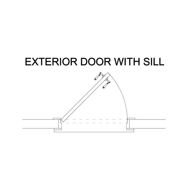
This is also where the external ground level relative to the internal finished floor level gets shown, which matters enormously for a threshold detail exactly like the one covered earlier in this series, an external door sill sitting at the wrong relative height to the ground outside is a defect that a wall section, read carefully, would have caught before construction started.
The foundation type itself changes how much of this bottom portion the section actually needs to show. A simple strip foundation under a low-rise domestic wall might only need a modest depth of concrete drawn below the wall, while a raft foundation spreads a continuous slab under the whole footprint and shows very differently in section, and a pile foundation, common on poorer ground, shows the wall sitting on a ground beam that in turn bears onto piles driven or bored well below what the section sheet can even show at a normal scale, usually requiring its own separate structural detail referenced off the main wall section rather than drawn in full. None of that changes how you read the drawing, foundation, floor buildup, wall, opening, roof, bottom to top, but it's worth knowing the foundation type shown is a genuine structural decision made for that specific ground condition, not an arbitrary drafting choice.
Climbing the wall: structure, insulation and openings
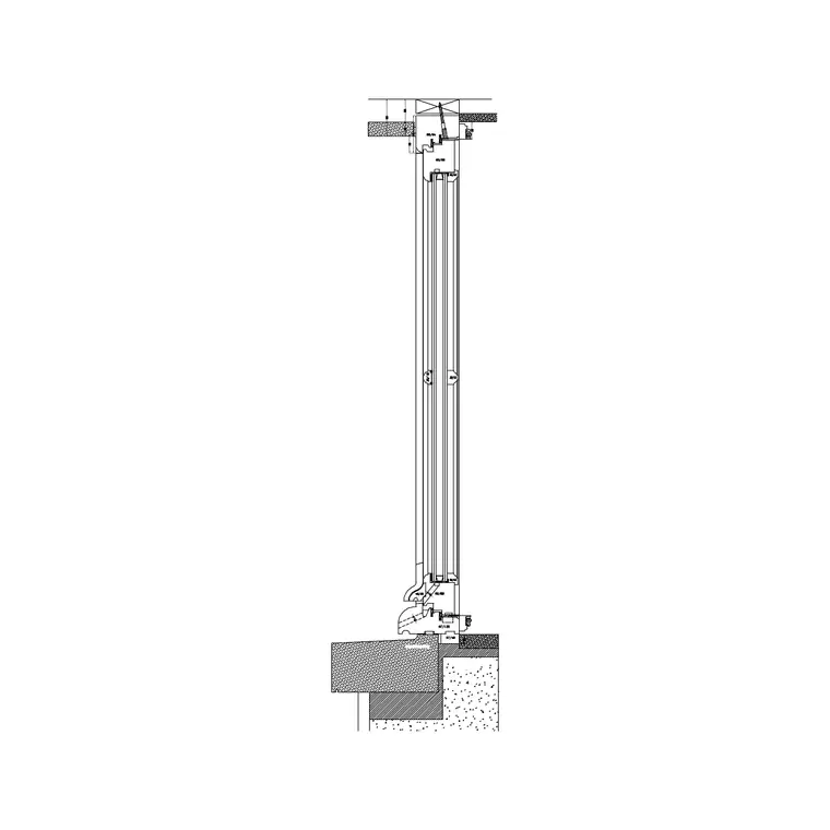
Moving up through the wall itself, the section shows the structural leaf (blockwork, brick, timber frame or concrete, depending on construction type), any cavity and insulation layer, and the internal lining, plasterboard or render, each drawn as its own line with its own hatch. Where the section line happens to pass through a door or window opening, this is exactly where the frame, sill, and head details covered earlier in this series show up, drawn in context within the larger wall buildup rather than isolated as their own zoomed-in detail.
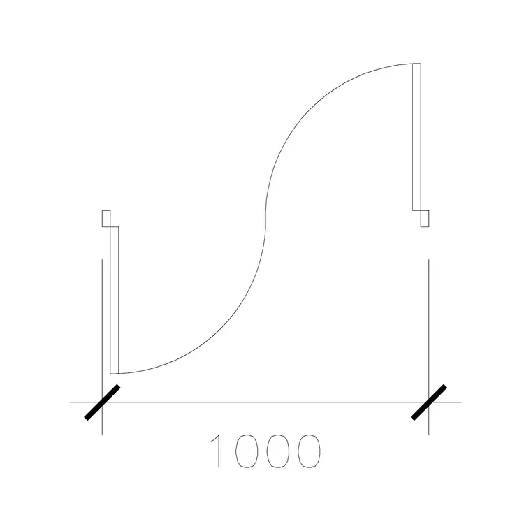
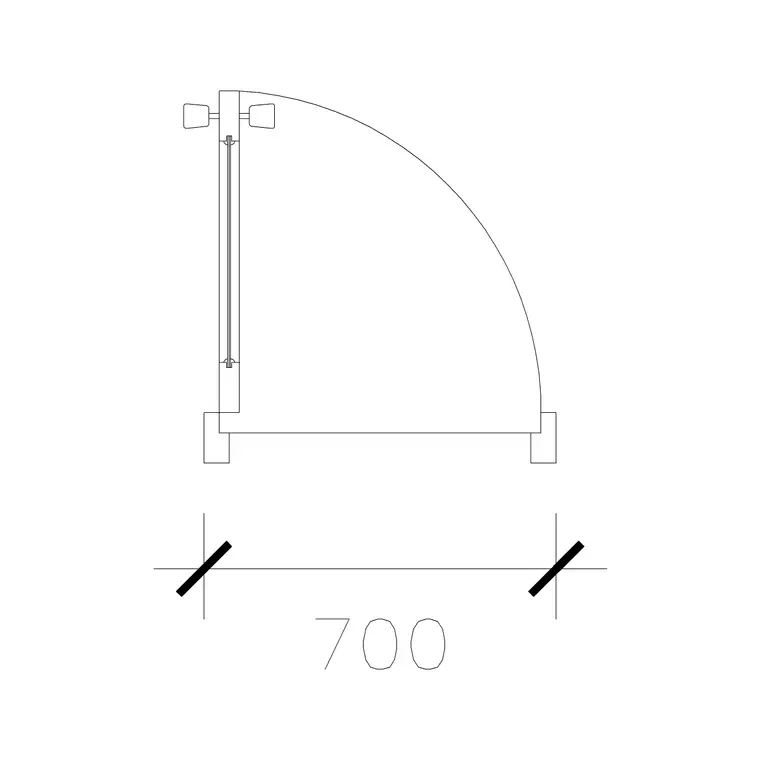
So if you're placing a door plan block like 1000 Mm Door Type 1 in your floor plan, or a window plan block like Window Plan (1) in the same area, the wall section is the drawing that shows how that same opening actually sits within the full wall thickness, vertically, which is information neither the plan nor the elevation carries on its own. Reading a section next to the matching plan and elevation, tracing the same opening across all three, is genuinely one of the fastest ways to build real fluency in construction drawings.
Cavity wall construction, still one of the more common wall types in a lot of residential building, is worth understanding specifically here because it changes what "the wall" even means in a section. Rather than a single solid thickness, a cavity wall is really two separate leaves, an outer leaf (often brick or block) and an inner leaf (block or timber frame), with a gap between them, at least partly filled with insulation, and tied together at intervals with metal wall ties so the two leaves act together structurally without the cavity itself being bridged by anything solid enough to carry water across. In section, that shows up as two distinct hatched zones with a clear gap and small tie symbols between them, and it's exactly why the cavity tray detail mentioned in the window sill post in this series exists at all, to stop water that gets into that cavity from finding a bridge across to the inner leaf at a vulnerable point like a window opening.
Where a stair intersects a wall section
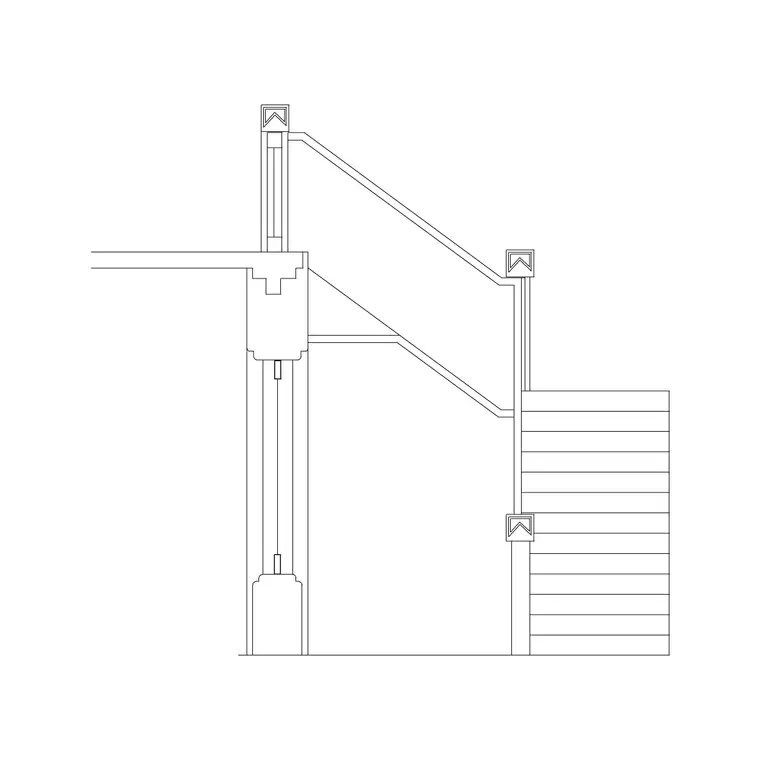
If the section cut happens to pass through a staircase, and on a multi-storey building it very often does, you'll see the flight in profile, the going and riser stepping up between floor levels, exactly the relationship covered in the staircase detail post in this series, along with the structural floor or landing it lands on partway up. This is one of the clearer illustrations of why a section is such a distinct drawing type from a plan, a stair plan shows tread outlines looking straight down, useless for judging headroom, while the section shows the actual vertical stepping and the critical headroom clearance underneath the flight above, which a plan literally cannot represent.
A metal staircase block like Metal Staircase Front Elevation 1 gives you the elevation view of a flight, useful for overall proportion, but a true wall section cutting through that same stair location would show the flight in the context of the surrounding wall and floor structure at every level it passes, a genuinely different piece of information from either the plan or the standalone elevation.
Reaching the top: roof structure and eaves
Follow the wall up far enough and the section reaches the eaves, the point where the wall meets the roof structure, and this junction carries its own dense little cluster of information, the wall plate the roof rests on, the roof structure itself in profile (rafters or trusses, drawn as a repeating angled line), insulation continuing up into the roof void, and a soffit and fascia closing off the gap underneath the overhang. Ventilation matters here too, a gap is usually left at the eaves specifically to let the roof void breathe, and on a well-drawn section that gap is called out explicitly rather than left implied.
What's worth noticing is that the eaves detail follows exactly the same logic as every other junction in this series, the door threshold, the window head, the kerb line, a point where two different building elements meet and something has to be resolved, structurally, thermally, or against water. A wall section is really just a continuous chain of these junctions, foundation to eaves, drawn as one uninterrupted vertical cut rather than as separate isolated details.
External works meeting the wall at ground level
At the very bottom of the section, where the wall meets the ground outside, you'll often see exactly the kind of external works detailing covered in the kerb and edging post in this series, a paved path or apron running up to the building, possibly with a slight fall away from the wall for drainage, and a kerb or edge restraint defining where that paving stops. A paving block like Paving Block 1 gives you the surface pattern in plan for that external area, but the wall section is what shows the actual relationship between the external ground level, the paving buildup, and the internal finished floor level, which is exactly the coordination point that goes wrong most often between the building design and the external works design when they're produced by different people.
Checking that the levels agree at this junction, external paving, damp-proof course height, internal floor level, is one of the single most valuable habits a beginner can build early, because it's an error that's cheap to fix on paper and expensive to fix once the concrete's poured.
A practical way to build fluency reading sections
The fastest way to actually get comfortable with wall sections, in my experience watching people learn this, is not to try to absorb an entire section at once but to trace one continuous element top to bottom first, follow the external wall face as a single line from the roof down through to the foundation, note every material change along the way, and only then go back and layer in the openings, doors, windows, stairs, cut through it.
- Identify ground level and finished floor level first, they're your two reference lines for everything else - Trace the external wall face as one continuous line from top to bottom before worrying about internal layers - Cross-reference every opening in the section against its matching plan block, door or window, to confirm widths agree - Check that damp-proofing and insulation layers are continuous, a break in either is a real, not cosmetic, defect - Note where the section cuts through a stair or a significant change in floor level, and check headroom specifically at that point
It's also worth being patient with yourself the first several times through, because a wall section genuinely does reward repeated exposure more than almost any other drawing type in a set. The first section you trace properly, layer by layer, foundation to eaves, will probably take a while and feel laborious. The tenth one goes noticeably faster, not because the drawings get simpler but because the pattern, ground level, floor buildup, wall structure, opening, lintel, roof structure, eaves, becomes familiar enough that you're scanning for what's different from the last one rather than starting cold every time.
Bringing plan, elevation and section together
At the end of the day none of plan, elevation or section works as a standalone drawing on a real project, they're three views of the same physical building, each carrying information the others can't. A door plan block tells you width and swing, an elevation tells you appearance, and a wall section tells you how it's actually constructed at that point, the exact same layered relationship covered across every post in this series, threshold and frame, sill and head, going and riser, kerb and edging, all of it eventually gets stacked into and read through the wall section. Once you can trace a single opening or a single junction across all three drawing types confidently, reading any full construction set gets dramatically easier, because you're no longer looking at three separate documents, you're looking at one building from three angles.
That's really the goal behind reading construction drawings at all, not memorising what any single symbol means in isolation, but building the habit of asking which drawing type would actually answer the question in front of you, plan for location, elevation for appearance, section for construction, and going straight to it rather than guessing from the wrong view.
Further reading
Questions
Frequently asked
What is a wall section drawing used for?+
A wall section is a vertical cut through a building's wall, from foundation to roof, showing every construction layer, structure, insulation, damp-proofing, finishes, that a plan or elevation cannot show. It's typically the drawing a contractor references most often on site.
How is a wall section different from an elevation?+
An elevation shows what the building looks like from outside, a flat view of the finished surface. A wall section cuts through the wall to show the actual construction buildup behind that finished surface, layer by layer, from ground level to roof.
Where do door and window plan blocks fit into a wall section?+
Where a section line happens to cut through an opening, the frame, sill and head detailing for that door or window shows up within the wall section in context. The plan block, like 1000 Mm Door Type 1 or Window Plan (1), gives you the width and swing for the floor plan; the section shows how that same opening sits within the full wall thickness vertically.
What's the best way to start learning to read wall sections?+
Trace one continuous element, usually the external wall face, from top to bottom first before trying to absorb every layer at once, then go back and check each opening or junction against its matching plan block to confirm the dimensions agree.
Free downloads from this article

Free CAD block library
Download the blocks from this article — free, no signup