Choosing window blocks for a cross ventilation diagram
How to pick and lay out window blocks so a cross ventilation diagram actually reads clearly, from opening placement to arrow conventions.
Sumana Kumar5 min read
A ventilation diagram lives or dies on opening placement
A cross ventilation diagram is one of those drawings that looks simple, a plan with some arrows showing air moving through, but it only tells the truth if the window blocks feeding it are placed and specified accurately, because the whole premise of cross ventilation depends on having genuine openings on at least two different walls, ideally on opposite or adjacent sides of a space, with a relatively clear path for air to travel between them. I've seen diagrams drawn with confident, sweeping arrows through a plan where the actual windows, once you check the blocks, were both fixed glass, which makes the whole diagram fiction rather than analysis.
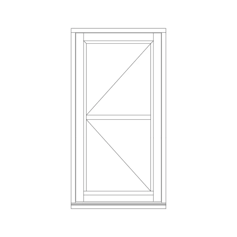
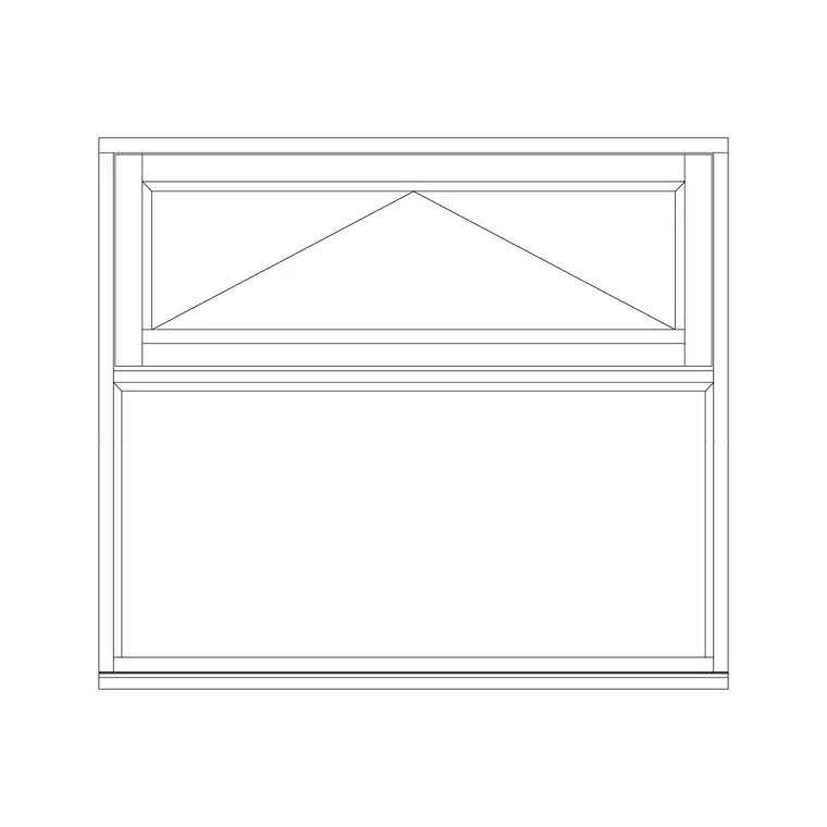
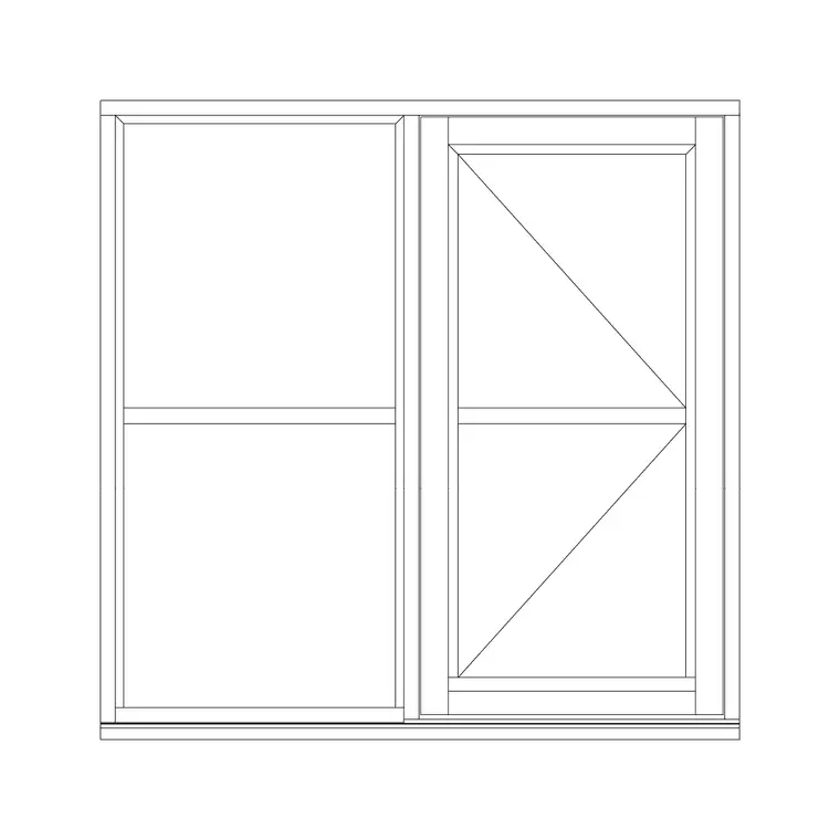
So before drawing a single arrow, confirm which window blocks on the plan are genuinely operable, single shutter, double shutter, 3 shutter or awning, because the diagram is only as honest as that underlying block selection.
Placing openings for a real cross path
For air to actually cross a room rather than just eddy near a single opening, you generally want operable windows on two walls that aren't directly adjacent and touching, opposite walls are the classic case, but two walls at right angles work too as long as there's a reasonably clear path between them without a wall of built in storage blocking the route. Offsetting the two openings rather than placing them dead centre and directly opposite each other tends to draw air across a larger portion of the room's floor area instead of funnelling it in a narrow, direct line, which is worth considering when you're deciding exactly where on each wall to place the window block.
I also think about what's between the two openings on the plan, furniture, partial walls, tall storage, because anything that blocks the direct sightline between the two operable windows is also going to disrupt the airflow path the diagram is trying to represent, so the furniture layout and the ventilation diagram really need to be developed together, not as two separate exercises.
Which mechanisms to use where on the diagram
For the intake side of a cross ventilation path, meaning the opening air is expected to enter from, a fully operable single or double shutter window tends to give the clearest, most generous opening, while the exhaust or outlet side can often be a smaller opening, an awning window works well here too, since the goal at that end is just to give the air somewhere to leave rather than maximise inlet area. This isn't a strict rule, but sizing the outlet a bit smaller than the inlet, or roughly matching them, tends to produce a cleaner, more legible diagram than two dramatically mismatched openings.
If one side of the intended path only has a fixed glass or a heavily fix glass dominant window available, the diagram needs to acknowledge that honestly rather than drawing an arrow through it anyway, either by revising the window selection on that wall if the design allows it, or by finding an alternative path, a door, a different window, that genuinely supports the airflow the diagram claims.
Drawing conventions that keep the diagram legible
Keep the ventilation arrows on their own dedicated layer, separate from the window blocks, furniture and wall hatching, so the diagram can be turned on or off independently and doesn't clutter a construction plan that has other jobs to do. A simple, consistent arrow style, a single line with a clear arrowhead, sized proportionally to the width of the operable opening it's leaving from, communicates more clearly than elaborate curved arrows trying to show turbulence or eddies that you likely can't actually verify without a real airflow simulation.
Label each operable opening on the diagram with its type, awning, single shutter, double shutter, so a reviewer can immediately see why that particular opening is or isn't contributing much to the flow, rather than having to cross reference back to the window schedule to understand the diagram. I also avoid stacking too many arrows on a single small plan, since a diagram trying to show every room's ventilation path at once tends to turn into visual noise, and splitting a busy floor plan into a couple of focused ventilation diagrams by wing or by zone almost always communicates more clearly than one crowded sheet trying to do everything.
Checking the diagram against real block proportions
At the end of the day, an arrow's visual weight on a diagram should roughly reflect the real operable area of the window block it's leaving, so don't draw a bold, wide arrow out of a small awning window and a thin one out of a wide 3 shutter opening, that inverts the actual relationship and misleads anyone reading the drawing quickly. I keep a rough mental scale, wider operable opening gets a proportionally wider arrow base, which keeps the diagram visually honest even without running a full quantitative airflow model behind it.
This matters most when a diagram is going in front of a client or a reviewer who isn't going to dig into the underlying block specs, the visual should already be telling them the truth about which openings are doing the real work.
Building it from accurate blocks
Insert the actual specified window blocks with INSERT, confirming units and scale so the openings on the plan are the real widths feeding your diagram, not an eyeballed placeholder. Where the design uses fix glass combination blocks like the single shutter with fix glass or awning with fix glass options, make sure your diagram is reading only the operable portion of that block as the source of the arrow, not the full visual width of the opening.
Once the underlying window blocks are accurate and correctly classified, the diagram itself is quick to build, and it holds up far better under scrutiny than one drawn from placeholder rectangles with arrows added after the fact for effect. Once the diagram is built this way, it also becomes a genuinely useful tool during design review, because a client or a consultant looking at honestly proportioned arrows sourced from real operable areas can trust what they're seeing, rather than having to take the airflow claim on faith the way they would with a purely illustrative diagram drawn free hand over a floor plan.
Further reading
Questions
Frequently asked
Do the two openings in a cross ventilation diagram need to be directly opposite each other?+
Not necessarily, opposite walls are the classic case, but adjacent walls at right angles can work too as long as there's a reasonably clear path between them, and offsetting the openings slightly often draws air across more of the room than a dead centre pairing.
Should a fixed glass window ever appear in a ventilation diagram?+
Only as context, never as a source of airflow, since fixed glass contributes no ventilation. If it's the only opening on a wall the diagram needs, that wall genuinely isn't part of the cross ventilation path and the diagram should reflect that honestly.
How should arrow size relate to window type on the diagram?+
Roughly proportional to the real operable area of that opening, so a wide, fully operable shutter window should get a visually wider arrow than a small awning vent, keeping the diagram's visual weight honest against the actual block sizes.
Free downloads from this article
Free CAD block library
Download the blocks from this article — free, no signup