Schematic design vs construction documents: block detail
How much CAD block detail belongs at schematic design stage versus construction documents, and why swapping blocks late is a workflow, not a shortcut.
Saumyajit MaityUpdated 19 April 20265 min read

Detail level is a decision, not a default
One of the habits I had to unlearn early in my drafting career was reaching for the most detailed block available every single time, because more detail feels like more professionalism when actually it's usually just more noise. A schematic design drawing that's carrying full hardware call outs and dimensioned nosing profiles on every stair is slower to produce, slower to redline, and honestly harder for a client to read at the stage where they're still deciding whether the stair goes here or over there. Block detail should track the decisions that have actually been locked, not run ahead of them.
So the real skill isn't knowing where to find a detailed block, it's knowing which stage of the drawing set that detail belongs in, and building your block library so you can dial the resolution up or down without redrawing from scratch each time.
What belongs at schematic design
At SD stage you're still testing options, so blocks should be simple, generic and fast to place, mostly single line or double line representations that communicate footprint and swing without committing to a manufacturer or a finished spec. A door at this stage just needs to show it exists, its rough leaf width and which way it swings, nothing more. Furniture and fittings can be block outlines with minimal internal linework, and a staircase can be a simplified plan symbol showing the number of risers and the general run direction without every tread dimensioned.
The point of this restraint is speed of iteration, because if a room layout changes twice in a design review meeting you want to be moving simple blocks around, not editing dimension strings buried inside a heavily detailed insert.
What construction documents actually need
By the time you're issuing for construction, that same stair needs real dimensions, going and riser figures within the typical domestic range of roughly 220 to 260 millimetres going and 150 to 220 millimetres riser depending on your local building regulations, a handrail height called out, and if it's something like a circular stair, the plan geometry needs to be accurate enough that a joiner can set out from it directly. A door at CD stage needs leaf and frame dimensions, hardware type, fire rating if applicable, and threshold detail, none of which matters at SD but all of which matters enormously once someone is pricing or fabricating from the drawing.
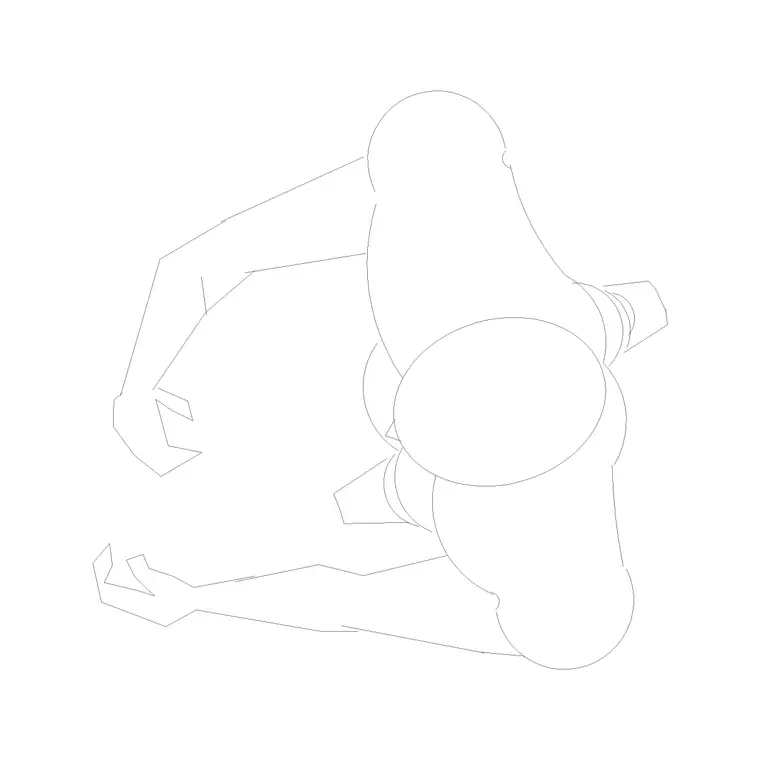
The wheel chair accessible symbol is a good example of this shift too, at SD it just marks intent, at CD stage the actual bay or clearance zone around it needs to be dimensioned to the regulation clearance your jurisdiction requires, because a contractor can't build to a symbol, they build to a dimension.
Windows follow the same curve, at SD a window opening might just be a hole in the wall with a rough width noted, useful only for massing and daylight testing, while at CD stage it needs a full window schedule reference, frame material, glazing spec, cill height and head height, tied back to a numbered tag on the elevation. I keep a simple two tier block set for openings exactly for this reason, a schematic void block for early testing and a fully annotated window block once the schedule is locked, and swapping between them follows the same purge and replace habit as the stair example above.
The swap out workflow, not an add on
The mistake I see junior drafters make is trying to evolve a schematic block into a construction block by just adding more lines to the same insert, which usually leaves ghost geometry behind and bloats the block definition. What I actually do when a project moves from SD to CD is treat it as a deliberate swap, I insert the detailed replacement block on the same insertion point and layer, verify it lines up, then purge the old simplified block definition out of the drawing entirely with PURGE so it's not sitting in the block table confusing the next person who opens the file.
This matters more than it sounds like it should, because a drawing carrying both the SD stair symbol and the CD stair block, even if only one is visible, adds file weight and creates real risk that someone toggles a layer back on by accident and suddenly the wrong stair is showing in a printed set.
Layering and scale by phase
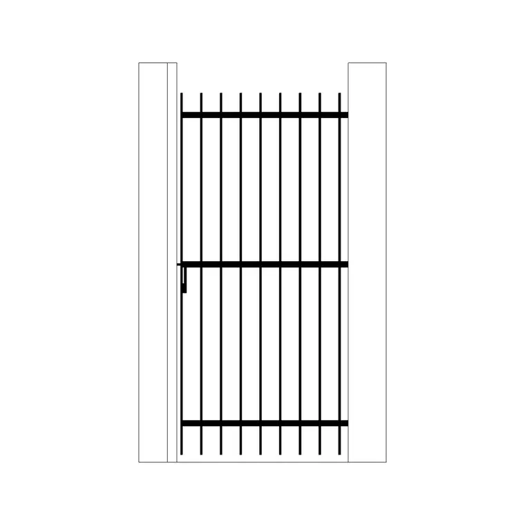
Detail level and plot scale are connected, and it's worth matching them deliberately. Schematic drawings are usually plotted at 1:100 or 1:200, scales where fine hardware detail wouldn't even be legible on paper, so there's no benefit to including it. Construction detail drawings often step down to 1:20 or 1:5 for the areas that need it, a stair section or a gate detail for instance, and that's exactly where the fully dimensioned block belongs, not smeared across every 1:100 general arrangement sheet where it just clutters the view.
Keeping schematic and detailed versions of recurring elements on separate layers, even during the transition period between stages, gives you a clean way to freeze one and thaw the other rather than hunting through the drawing for stray geometry.
A rule of thumb for how much is enough
The test I use is simple: if someone could build or price directly from this block, it belongs at CD. If it only needs to communicate intent to a client or a planning reviewer, it belongs at SD, and adding more than that is wasted drafting time you won't get paid for twice. Right sizing the detail to the stage is genuinely one of the highest leverage habits a drafter can build, because it protects your hours on early stage work and makes sure the detail you do add later is the detail that actually earns its keep on site.
I've handed over schematic sets carrying fully detailed hardware schedules more than once early in my career, thinking it showed diligence, and every time it just meant redoing the same work twice when the layout inevitably shifted before the client signed off. Save the detailed block for the moment the decision is actually locked, and you'll draft faster at every stage of the project, not just the early one.
Further reading
Questions
Frequently asked
Should I use the same block for schematic and construction stage drawings?+
Not usually. It's cleaner to swap a simplified schematic block for a fully detailed construction block at the point the design is locked, then purge the old block definition so you're not carrying redundant geometry in the file.
What plot scale is construction detail usually drawn at?+
General arrangement drawings tend to sit at 1:100 or 1:50, while construction details for things like a stair section or a gate fixing typically step down to 1:20, 1:10 or even 1:5 where the tolerances matter.
How do I know if a block is too detailed for early design stage?+
If it's slowing down how fast you can move or resize the element during a design review, or the linework isn't even legible at the scale you're plotting, it's carrying more detail than the stage needs.
Free downloads from this article

Free CAD block library
Download the blocks from this article — free, no signup