Setting Out a Multi-Storey Car Park Ramp: Gradient Rules
How to set out a multi storey car park ramp, typical gradient limits, transitions and headroom, checked against real vehicle CAD blocks.
Sumana Kumar11 min read
Why a car park ramp is a geometry problem, not just a slope
Setting out a car park ramp gets treated sometimes as a single number problem, pick a gradient, draw the slope, but a working ramp is really a chain of several interacting decisions: the gradient itself, the transition where that gradient meets a flat floor at each end, the headroom available at every point along the slope, and the width needed for the vehicles actually expected to use it. Get the gradient right but skip the transition detail, and you'll design a ramp that scrapes the underside of every low slung car that uses it, a detail that's genuinely more common in a first draft than people expect.
A ramp is also usually one of the last things fully resolved on a multi storey scheme, right, because its geometry depends on decisions, floor to floor height, structural grid, overall footprint, that themselves get finalized fairly late in the design process. That sequencing is exactly why it's worth flagging ramp gradient and length as an early stage constraint rather than a detail to solve once everything else is fixed, since a floor to floor height chosen without checking it against a workable ramp length is a difficult problem to unwind later.
Typical maximum gradients for straight ramps
Most car park design guidance caps a straight ramp gradient somewhere around 1 in 10, roughly 10 percent, or about 5.7 degrees, for a ramp regularly used by ordinary cars, with some guidance allowing slightly steeper for short runs and others recommending a gentler 1 in 12 or 1 in 15 where the ramp is long or used heavily. The steeper end of that range is workable for most vehicles in dry conditions but becomes noticeably less comfortable, and less safe, for a driver in wet or icy conditions, or for a longer wheelbase vehicle that's more prone to grounding on a gradient change, which is exactly why the transition sections covered next matter so much.
A ramp that will regularly be used in icy or snowy conditions is often designed toward the gentler end of the range regardless of how long or short it is, since surface grip, not just vehicle geometry, becomes the limiting factor once ice is a realistic possibility. Some schemes also add surface heating or a textured, higher grip finish specifically on the ramp run for exactly this reason, which is a specification decision worth flagging early since it affects the finished surface thickness and detailing at the ramp's edges.
A worked example: checking whether a floor to floor height gives a workable ramp
Say a scheme has settled on a floor to floor height of 3 meters for structural and services reasons, and the available run for a straight ramp between two levels is a fixed 24 meters before it has to turn a corner into the next bay of the structure. Working backward from a 1 in 10 maximum gradient, climbing 3 meters over that gradient needs a minimum ramp run of 30 meters before you even add the transition sections at each end, which immediately tells you the straight run doesn't fit in the 24 meters available and something has to change, a gentler floor to floor height, a longer available run, or a switch to a curved or helical ramp that trades some of that length for a turn instead.
This is exactly the kind of check worth running early, on the back of an envelope if that's all the design stage allows, rather than waiting until a full ramp detail is drawn to discover the numbers don't actually close. Once the basic length versus gradient arithmetic checks out, that's the point to add the transition sections at roughly half gradient, re-run the length check with those included, and only then move on to checking width, cross fall and headroom along the confirmed length, since there's little point refining those finer details around a ramp length that doesn't actually fit the site in the first place.
Transition or kick sections at the top and bottom
The gradient change at the top and bottom of a ramp is rarely a single sharp break from flat to full slope, because that sharp break is exactly where a car's front or rear overhang grounds out as it crosses the change. Instead, most design guidance calls for a transition or kick section, typically run at roughly half the main ramp's gradient for a short length, often somewhere in the 2 to 3 meter range, easing the vehicle into and out of the full gradient gradually rather than abruptly. Skipping this transition, or making it too short, is one of the more common ramp design mistakes, since it looks like a minor detail in a longitudinal section drawing but produces an audible, embarrassing scrape on the finished ramp the first week it's open.
Helical and curved ramps
Where a ramp also needs to turn, common in a compact multi storey structure where a straight ramp run isn't available, a helical or curved ramp lets the vehicle climb while turning rather than needing a separate straight climbing section plus a separate turn. Curved ramps are typically designed to a gentler maximum gradient than an equivalent straight ramp, often in the 1 in 10 to 1 in 12 range or flatter, because a vehicle is negotiating a turn and a slope simultaneously, and the combined demand on tyres and suspension geometry is higher than either movement alone. The outer lane of a curved ramp also needs to be checked separately from the inner lane, since the outer lane's actual travel distance, and therefore its effective gradient behaviour, differs from the inner one.
An alternative to a single continuous helical ramp, common in some multi storey structures, is a split level or scissor ramp arrangement, where two separate half level floor plates are connected by a shorter ramp run between them rather than one long continuous spiral. This can reduce the length of any single ramp run and therefore the cumulative gradient challenge, though it adds its own complexity in floor plate layout and wayfinding, since a driver needs clearer signage to understand which half level they're actually on.
Cross fall, drainage and sightlines where the ramp meets a flat floor
A ramp surface also needs a cross fall, a gentle slope across its width rather than just along its length, so rainwater or washdown water actually runs off to a drainage channel rather than sheeting straight down the ramp's full length and pooling at the bottom. This is usually a modest cross fall, enough to move water without being noticeable to a driver, and it's typically paired with a drainage channel or gully at the low point, most often right at the base of the ramp where a flat floor begins, since that's exactly where water arriving from the whole ramp length above will otherwise collect.
That same point, where a ramp meets a flat parking floor, is also a common conflict point between a descending or ascending vehicle and a pedestrian walking across that floor, because a driver's sightline down or up a ramp is genuinely limited compared to sightlines on a flat, open floor plate. Many multi storey schemes address this with a convex mirror positioned to show a driver what's around the corner at the top or bottom of a ramp run, combined with a painted pedestrian route that avoids crossing directly in the ramp's path wherever the floor layout allows it. It's a detail worth resolving at design stage rather than leaving to signage alone, since a sign asking a pedestrian to look both ways doesn't actually fix a sightline a driver never had in the first place.
Headroom and the vertical clearance chain
Every point along a ramp's length needs its own headroom check, not just a single figure taken at the flat floor level, because the available vertical clearance under a beam or a services zone changes as the ramp climbs relative to a fixed structural soffit above it. A minimum clearance is typically maintained throughout at a figure that comfortably clears the tallest vehicle type the car park is designed for, commonly checked against a nominal SUV or van height with a margin for services, sprinkler pipes, ductwork, signage, hanging below the structural soffit, since the structural clearance and the actual usable clearance are two different numbers once services are installed.
The tightest headroom point on a ramp usually isn't where you'd first guess, right, it's often not the very top or bottom, but somewhere partway along the slope where the rising floor plate gets closest to a fixed structural beam or a service run that hasn't been coordinated to follow the ramp's own rising profile. Checking headroom purely at the two ends of a ramp and assuming the middle is fine by extrapolation is a common and entirely avoidable way to miss the actual pinch point on a longitudinal section drawing.
It's worth building a simple check for this rather than relying on a single spot height figure: take the ramp's own rising profile as a straight line in section, then overlay the underside of the lowest services run, ductwork, sprinkler mains, cable tray, as its own line in the same section, and look for the point where the vertical gap between the two lines is smallest rather than assuming it's automatically at either end. On a lot of real ramp sections that minimum gap actually falls somewhere around a third to halfway along the slope, precisely because that's where a services run installed on a level ceiling grid is closest to a floor surface that's already risen partway toward the next level. Flagging that point explicitly on the section drawing, with a dimensioned clearance figure right at it rather than only at the ramp's two ends, is a small addition that catches a genuine clash long before it becomes a site problem discovered by a services installer holding a tape measure.
Ramp width and whether it's one way or two way
Ramp width depends entirely on whether it's designed as one way or two way. A one way ramp, common in compact urban structures where space is at a premium, can be narrower, but needs unambiguous signage and often a physical or electronic control system to prevent a vehicle entering against the flow, since a head on meeting on a sloped, curved ramp is a genuinely dangerous scenario. Traffic light control at each end, tied to a sensor loop or timer, is a common way to enforce a one way ramp without relying purely on a driver reading and obeying a sign, particularly where the ramp is long enough that a driver partway along it can't simply reverse back out if they meet an oncoming vehicle. A two way ramp needs roughly double the width of a one way lane, plus often a center divider or clear line marking, and is the safer default wherever the site has room for it, removing the directional control problem entirely rather than managing it.
It's also worth allowing a short flat landing area at the top and bottom of a ramp run before any barrier, ticket machine or gate, rather than positioning that control equipment directly on the sloped section itself, since a vehicle stopped on a slope to interact with a ticket machine is both an uncomfortable experience for the driver and a genuine hazard if the vehicle rolls before the driver re-engages the brake.
Checking a ramp layout against real vehicle CAD blocks
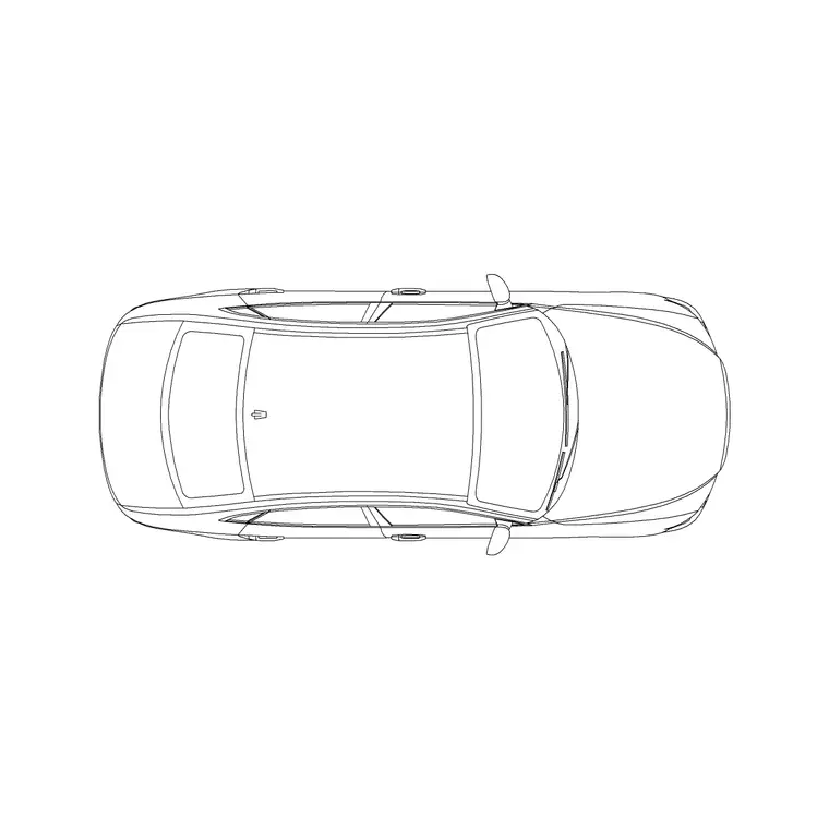
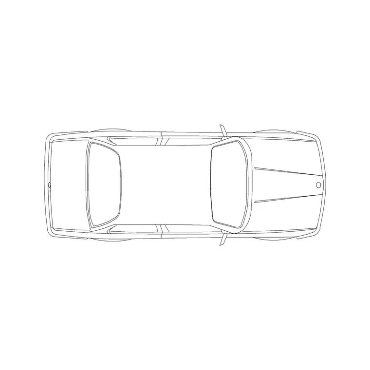
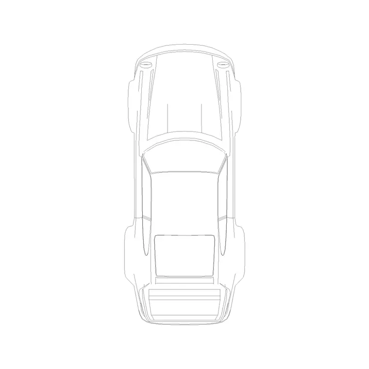
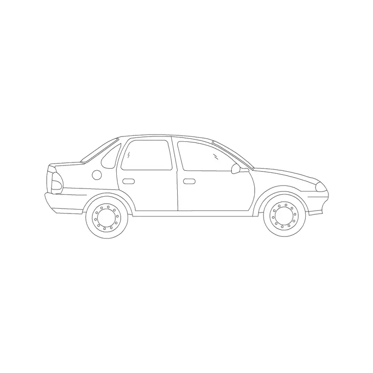
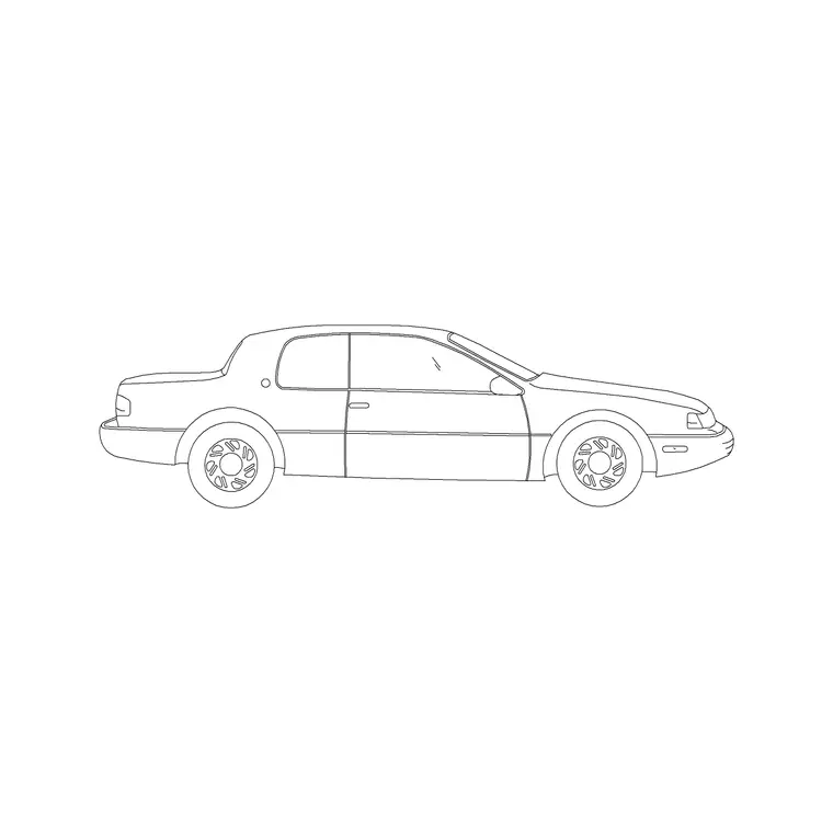
Before committing to a ramp width and gradient on the drawing, it's worth placing our vehicle plan blocks, car-plan-7, car-plan-8 or the suv-car-plan-7 for a taller vehicle check, into the ramp width at a few points, particularly through any curved section, to confirm the swept path actually clears both lane edges with a sensible margin rather than trusting a generic width figure. For the ramp surface itself, our paving blocks, paving-block-1 for instance, are useful for representing the finished surface, keeping in mind the actual non slip surface specification for a sloped ramp is a materials decision separate from the CAD block representing its appearance.
Run this same plan view check at the transition sections too, not just the main gradient run, since the transition is exactly where a vehicle's front or rear corner overhangs furthest relative to its own wheelbase, and a width that reads comfortable on the straight slope can still feel tight the moment a vehicle is also easing through the kick at either end.
Common mistakes
- Specifying a maximum gradient without designing a proper transition section at each end, leading to grounding - Checking headroom only at the flat floor level rather than along the full sloped run - Sizing ramp width for cars only, then finding a taller van or SUV needs re checking against the same headroom figure - Designing a one way ramp without a robust way to actually prevent wrong way entry - Forgetting cross fall and a drainage channel at the base of the ramp, leaving standing water at exactly the point vehicles need the most tyre grip - Positioning a ticket machine or barrier on the sloped section of the ramp rather than on a flat landing area at the top or bottom - Fixing floor to floor height and overall footprint before checking whether a workable ramp gradient and transition actually fit within them
Further reading
Questions
Frequently asked
What's a typical maximum gradient for a car park ramp?+
Many design guides cap a straight ramp at around 1 in 10, about 10 percent, for regular use, with gentler options like 1 in 12 or 1 in 15 recommended for longer or heavily used ramps.
Why does a ramp need a transition section?+
A sharp break between a flat floor and the full ramp gradient causes a vehicle's front or rear overhang to ground out. A transition or kick section at roughly half the main gradient eases the vehicle in and out of the slope gradually.
How wide should a car park ramp be?+
It depends on whether it's one way or two way. A two way ramp needs roughly double the width of a single one way lane, plus often a center line or divider, and is generally the safer default where space allows it.
Do you have car park ramp CAD blocks?+
We don't have a single ramp block since a ramp is really a set out geometry problem, but our vehicle plan blocks and paving blocks are useful for checking ramp width and surface against a real vehicle footprint.
Free downloads from this article

Free CAD block library
Download the blocks from this article — free, no signup