Operating Theatre Layout: OT Table, Pendant and Equipment Blocks
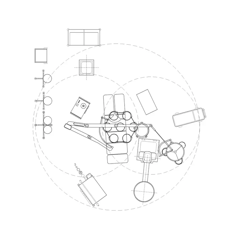
ot-table-with-pendant, the pendant blocks and generic machine symbols, and how they combine into a real equipment-dense OT floor plan.
Saumyajit MaityUpdated 22 July 202610 min read
One table, and everything else fighting for the same air
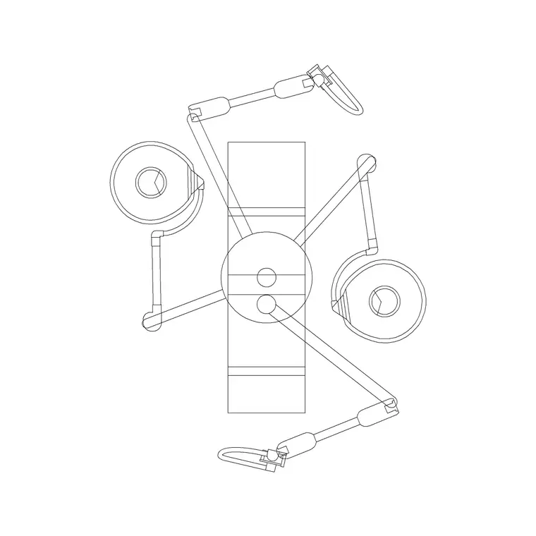
An operating theatre floor plan looks sparse compared to a ward, one table roughly at the center of the room, and if you counted actual pieces of drawn furniture you might get to four or five, but the equipment logic sitting on top of that empty-looking plan is the real content of the drawing, boom arms reaching down from the ceiling, a machine or two parked at the head end, a trolley within arm's reach of the surgical team, and all of it has to coexist in a room that usually cannot grow just because the equipment list did.
Our medical category has a specific run of blocks built for exactly this kind of room, ot-table-with-pendant, ot-equipment, four separate pendant symbols, three generic machine blocks and a matched elevation pair for showing them against a section, and the honest way to use them is less like decorating a room and more like solving a clearance puzzle where the table is fixed and everything else negotiates around it.
Compare that equipment density to a straightforward exam room or even a dental surgery, and the gap becomes obvious, most clinical rooms have one clear service zone and a predictable furniture count, while an OT room concentrates nearly all of its planning complexity into a single fixed point in space, the table, and every other decision in the room radiates outward from that one point, which is really why this room type deserves its own dedicated set of blocks rather than borrowing generic furniture symbols from elsewhere in the catalog.
ot-table-with-pendant as the anchor block
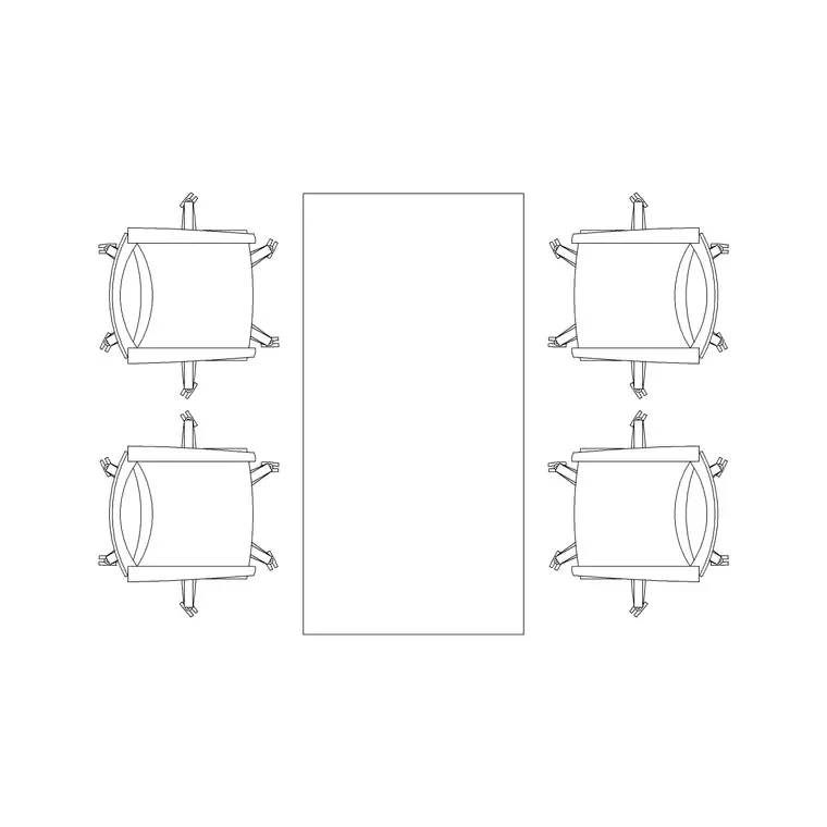
ot-table-with-pendant bundles the table and a suspended pendant reach in one insert, which matters early in a design because most architects reviewing an OT layout at schematic stage do not want to see the table drawn in isolation, they want to immediately understand how much ceiling-mounted reach is going to sweep over that table once real equipment is installed, and a bundled block answers that in one placement instead of two separate decisions.
The catch is that a bundled block still represents one generic configuration, and a real theatre often runs two or three pendants off different ceiling rails, one for the surgical light, one for equipment or monitors, sometimes a third for anesthesia gas and power, so treat the bundled block as your starting anchor and expect to add the separate pendant blocks around it once the room's actual service count is known.
It also helps early in a project to use the bundled block specifically as a conversation starter with the clinical planning team rather than a finished answer, because the actual number of pendants, their reach, and which rail each one runs on is usually a decision the hospital's own equipment planner makes fairly late in the process, so showing the anchor block on an early schematic sheet and labeling it as indicative gives the team something concrete to react to without implying the final pendant configuration has already been decided.
Four pendant blocks, and why more than one is normal
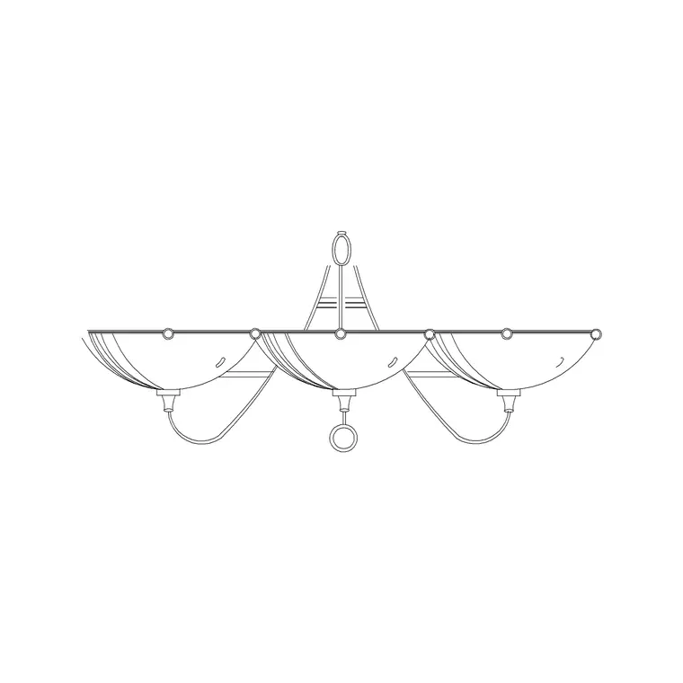
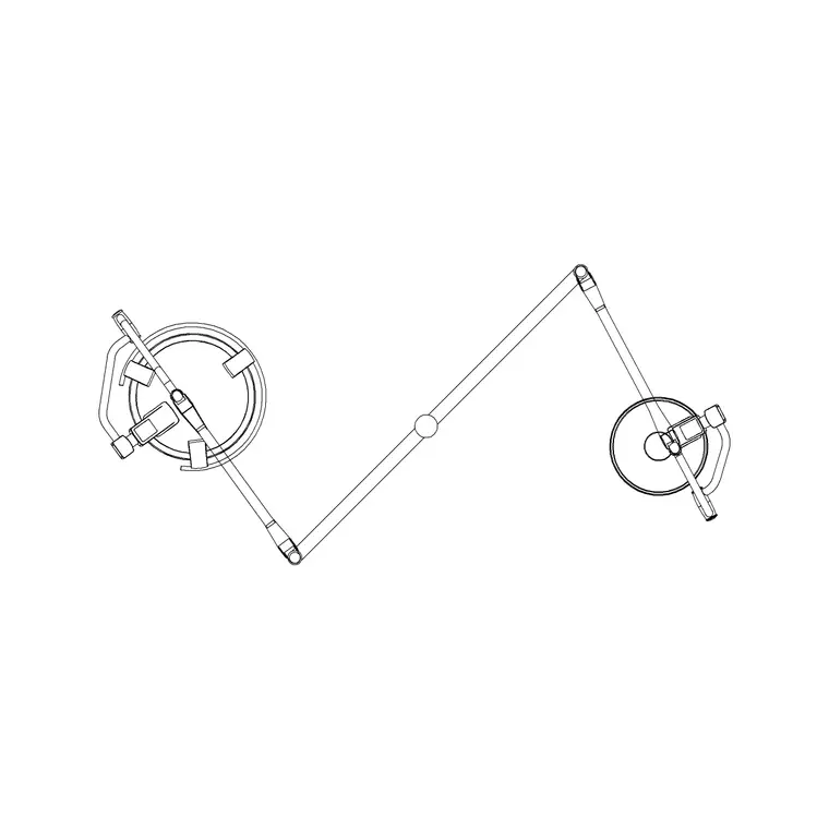
pendant-1 through pendant-4 are generic top-view pendant symbols at different footprints, and none of them are labeled by function because a ceiling pendant's job in real hospitals varies by manufacturer and by department more than a generic CAD library could ever capture, so the honest approach is to pick the block whose footprint is closest to the reach circle you actually need and label its function with a text callout rather than expecting the block name to carry that meaning.
Where this matters most is in an early room-sizing exercise, because two or three pendants each sweeping a meaningful reach off the ceiling can genuinely determine whether a piece of equipment fits on the floor beside the table at all, so I usually draw all the pendant reach circles before I finalize any fixed equipment position in the room, not after.
Because none of the four pendant blocks carry a function label, it is worth adopting a simple text-tag convention from the very first sheet you draw, something as basic as tagging each pendant with a small leader note naming its intended service, light, monitor, anesthesia or equipment, because once a floor plan has several rooms each with two or three pendants, an untagged set of identical-looking circles becomes genuinely hard for a reviewer to interpret correctly without asking you room by room what each one is for.
machine-1, machine-2, machine-3 and the elevation pair
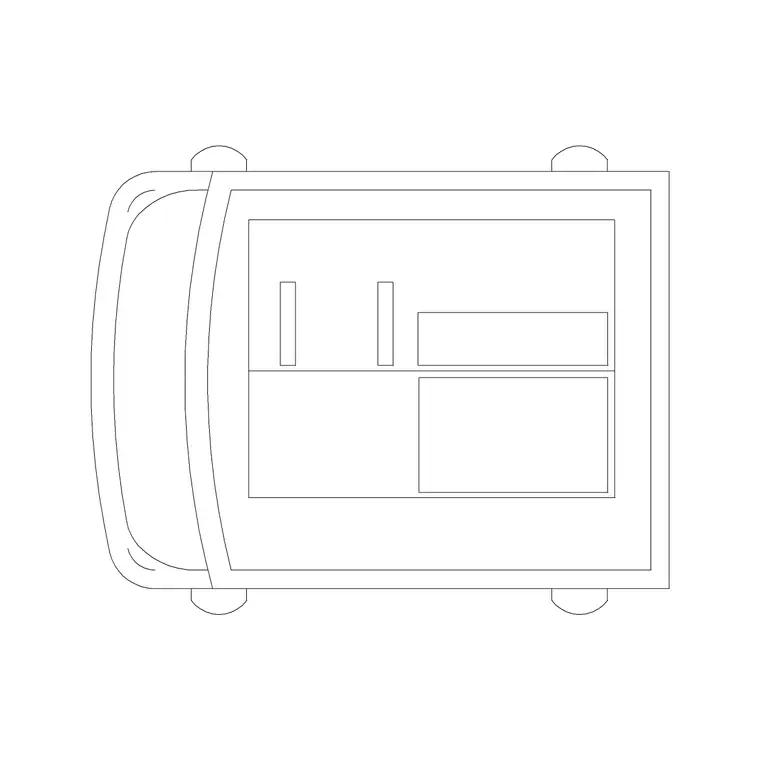
The three generic machine blocks exist as placeholders for whatever equipment actually needs floor space around the table, an imaging unit, an anesthesia cart, a monitor stack, and using a generic block here rather than trying to source a manufacturer-specific symbol is usually the right call at design stage, because the equipment brand is frequently not locked in until much later in the project.
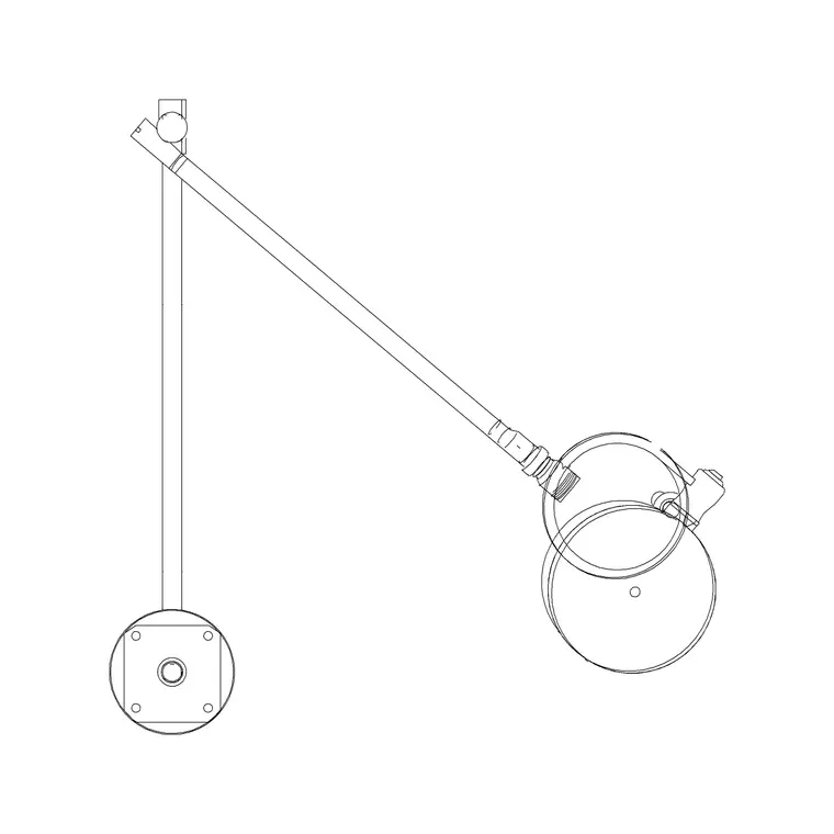
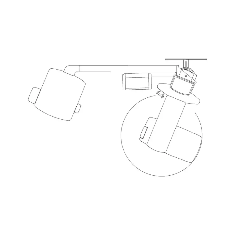
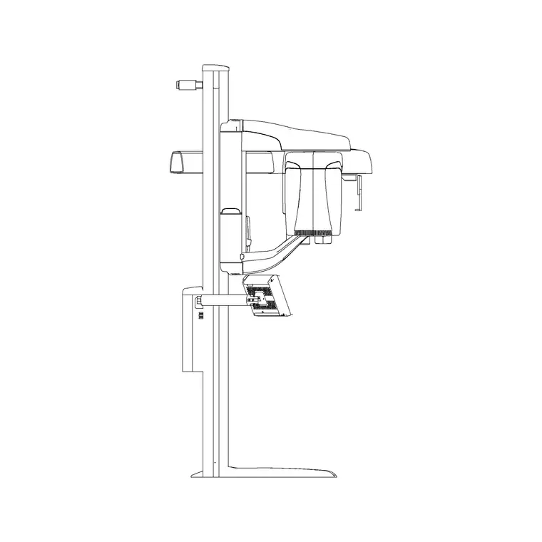
machine-stand-elevation and machine-stand-elevation-2 give you the matched vertical view, which is the drawing that actually settles ceiling rail height and boom reach against the floor equipment, and this is where orthographic projection earns its keep again, a plan alone cannot tell you whether a boom arm at full extension clears the top of a machine parked beneath it, only a coordinated section or elevation can, so pairing plan and elevation for this one room is worth the extra sheet.
The elevation pair is also the sheet most likely to catch a ceiling height problem before construction rather than during it, because a boom reach that looks perfectly reasonable in plan can turn out to conflict with a lowered ceiling bulkhead or a structural beam once it is actually drawn in section, and this is exactly the kind of clash that is cheap to fix on paper and expensive to fix once the ceiling grid is already installed, so treating the elevation pair as a required check rather than an optional extra sheet is worth insisting on for this room type specifically.
cath-machine and the neighboring cath lab, not quite the same room
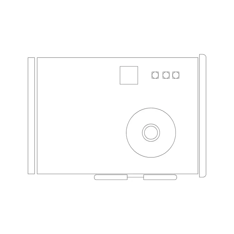
cath-machine sits in the same medical set and shares a lot of DNA with an OT layout, an imaging-heavy room built around one fixed table position, but a cath or interventional suite is genuinely a different room type with its own ceiling-mounted imaging arm and different clearance logic, and the honest note here is that cath-machine is the closest block we carry for that room, not a purpose-built cath lab symbol, so treat it as a starting placeholder the same way you would treat the generic machine blocks.
If you are drawing both an OT suite and a cath lab in the same project, which happens more often than people expect in a combined surgical and interventional department, keep the two room types on separate layers even if you are borrowing overlapping blocks between them, because the equipment logic that governs each room is different enough that merging them visually tends to confuse a reviewer.
The safest habit when a project genuinely needs a dedicated cath lab drawing rather than a borrowed OT layout is to flag cath-machine explicitly as a placeholder on the sheet itself, a short note saying the final equipment will be confirmed against the actual imaging vendor's own footprint and clearance drawing, because interventional imaging equipment varies enough between manufacturers that a generic block, however useful for early massing, should never be mistaken for a coordinated equipment drawing once the room moves toward construction documents.
circular-stand-1 and the mobile equipment ring around the table
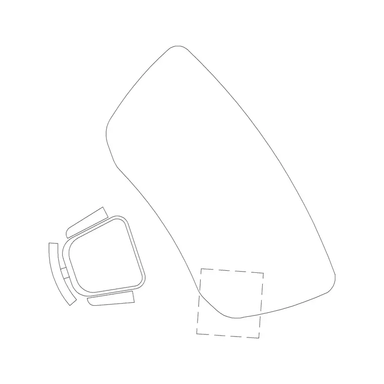
circular-stand-1 and its counterpart cover the mobile stands, IV poles and instrument stands that live within arm's reach of the table but are not fixed to the ceiling or the floor plan permanently, and drawing at least one or two of these near the table, even in a schematic layout, is what keeps a reviewer from assuming the room is emptier than it will actually be on a working day.
trolley is the other block worth keeping close to the table for the same reason, a mobile instrument trolley is one of the few pieces of equipment guaranteed to be present in every real theatre regardless of specialty, so even a fast massing layout benefits from including it rather than leaving that zone of the room blank.
It is also worth thinking about these mobile blocks as the elements most likely to move on any given day even after construction is complete, unlike the table and the ceiling pendants which are effectively fixed once installed, the stands and trolleys get repositioned constantly around whatever procedure is happening that day, so drawing them in a plausible resting position is more about proving the room has enough slack floor area to accommodate that daily shuffling than about pinning down one correct permanent location.
Drafting the room in a sensible order
The sequence I default to is the table on its centerline first, then the pendant reach circles drawn out to their full radius before anything else goes in, then the fixed machine positions checked against those circles, then the mobile stand and trolley positions filled in around whatever floor space is left, and only at the end do I add the elevation pair to confirm the ceiling coordination actually works in section.
Computer-aided design earns its keep in exactly this kind of layout, because the whole value of drawing in a CAD environment rather than by hand is being able to move a pendant reach circle a small amount and immediately see whether the machine block still clears it, which is a genuinely iterative process for a room this equipment-dense, and no OT layout survives first draft unchanged once the real reach and clearance numbers are checked against each other.
None of this sequence is rigid, and on a real project you will circle back through it more than once as the equipment list firms up, but starting from the fixed table and working outward through ceiling reach before floor equipment, rather than starting with whatever block happens to be open on your screen, is the difference between a layout that holds together once the real equipment list arrives and one that has to be substantially reworked the first time a piece of equipment does not fit where it was casually placed.
What this set of blocks is good for, and what it is not
This set of OT blocks is genuinely useful for the two things it is built for, proving that a room can physically hold the table, the ceiling services and the mobile equipment a real theatre needs, and communicating that footprint clearly enough for a clinical planner to react to it early, and for a schematic or early design development stage, that is exactly the level of detail a drawing should carry.
What it is not, and this is worth stating plainly, is a substitute for manufacturer equipment drawings once a project moves toward construction, the actual boom reach, table dimensions and machine footprint from whichever vendor gets specified will differ from these generic blocks by some margin, so the honest way to use this set is as the tool that gets a room correctly sized early, with the understanding that a final equipment coordination pass against real vendor drawings still has to happen before anything gets built.
That said, an early sheet drawn honestly from this set still carries real weight in a project, it is usually the first concrete evidence a clinical planning committee sees that the room they are asking for actually fits the shell they have been allocated, and getting that conversation started early with a reasonably accurate placeholder layout is worth far more than waiting for a fully vendor-coordinated drawing that may not exist until much later in the schedule.
Further reading
Questions
Frequently asked
Does ot-table-with-pendant include the surgical light, or do I still add a pendant block separately?+
It bundles the table with one suspended pendant reach as a starting anchor, but a real theatre commonly runs more than one ceiling pendant for light, equipment and anesthesia service, so add pendant-1 through pendant-4 around it once you know the room's actual service count.
What is the difference between the four pendant blocks?+
They are generic top view pendant footprints at different sizes rather than blocks tied to a specific function, so choose based on the reach circle you need and label the function in text, the block name alone will not tell a reviewer what service that pendant carries.
Do you have a block specifically for an anesthesia machine?+
Not one labeled that way, machine-1, machine-2, machine-3 and ot-equipment are the generic equipment placeholders in the set, which is honestly how most schematic-stage OT drawings handle equipment before a brand is locked in anyway.
Is cath-machine meant for an operating theatre or a cath lab?+
It is closer to a cath or interventional suite than a standard OT, though the two room types share a lot of the same equipment-around-one-table logic, use it as a placeholder and keep the two room types on separate layers if a project has both.
Free downloads from this article
Free CAD block library
Download the blocks from this article — free, no signup