Hospital Ward Bay Planning: Bed Spacing and Curtain Track Basics
Why bay spacing, not the bed block, decides a hospital ward layout, and how curtain, head-unit and basin blocks combine into a real bay.
Saumyajit MaityUpdated 4 July 202610 min read
The bed is rarely what breaks a ward layout
A ward layout got kicked back to me once, not because any single block was wrong, but because the bay as a whole came up short against the client's own space standard, every bed still fit on paper, it was the curtain lane that did not, and that is really the lesson this whole post is built around, the bed itself is rarely the thing that breaks a ward layout.
This is a planning-logic post more than a block-feature post, so let's be upfront about it, patient-bed-with-curtain, bed-with-bed-head-unit, curtain, wash-basin-plan, wash-basin-elevation, stand and trolley all live in our medical category alongside 36 products total, and none of them decide bay spacing on their own, spacing is a decision you make once, using the blocks as the vocabulary, not something any single block hands you automatically.
The space standard causing that particular bay to come up short was not exotic, it was actually stricter than the norm about door-swing clearance into the bay, which is a detail that is easy to miss if you are only checking bed footprint and curtain lane against a generic rule of thumb rather than the specific document governing that project, and it is the kind of miss that a quick early review would have caught for free instead of costing a full resubmission later.
What actually sets the repeat distance between bays
The instinct when you first lay out a multi-bed ward is to measure the bed and assume that number, plus a bit, is the repeat distance, but the real repeat unit is the bed footprint plus the curtain lane plus whatever aisle clearance the project's own space standard or local code actually requires, and in most wards I have drawn, the aisle and curtain allowance ends up being a bigger number than the bed itself.
Accessibility is one of the real drivers behind that aisle number, a ward that needs to accommodate a wheelchair-bound patient moving between the bed and the bathroom door, or a hoist being wheeled in, needs meaningfully more clearance than a ward that does not, so the space standard you are drafting against usually bakes universal design thinking into the aisle width long before you ever open AutoCAD, and the block layout just has to honestly reflect whatever that number turns out to be.
Worth noting too that the repeat distance is rarely uniform across an entire ward even within one project, a bay next to a fire door or a structural column often needs a slightly different allowance than a bay in the middle of a long straight run, so resist the temptation to lock one repeat number into a block array and assume it holds for every bay on the floor without checking the ones sitting next to an obstruction.
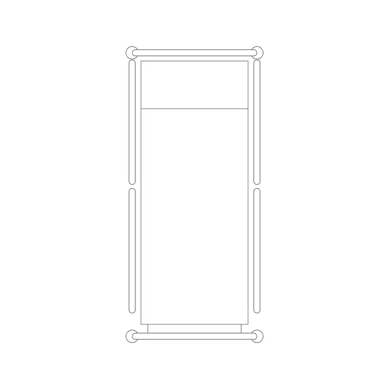
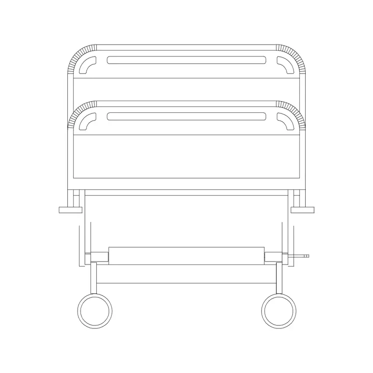
patient-bed-plan for the spacing review, patient-bed-elevation for the head wall
When a bay gets reviewed, the plan view is what answers the spacing question, does the curtain clear, does the aisle read wide enough, does the basin sit clear of the door swing, and patient-bed-plan is drawn specifically to sit cleanly inside that kind of furniture layout sheet rather than looking borrowed from somewhere else.
patient-bed-elevation answers a completely different question, what does the head wall actually look like once the bed, the service unit and whatever hangs above it are all stacked together in one vertical view, and skipping this view is one of the more common reasons a ward bay looks fine in plan and then runs into a clash once the head wall service run gets detailed properly, so treat the two views as a pair you check together, not one or the other.
A useful habit when reviewing a set of bay drawings is to physically place the plan sheet and the elevation sheet for the same bay side by side rather than reviewing them on separate pages days apart, because a lot of head-wall clashes only become obvious when you can see the plan's spacing decision and the elevation's vertical stacking decision in the same glance, and catching that at review stage is considerably cheaper than catching it once services are actually being installed on site.
bed-with-bed-head-unit, and being honest about what it actually shows
bed-with-bed-head-unit gives you the bed paired with the wall-mounted service unit behind it as one insert, which covers the massing question, how much wall length and how much depth that unit occupies, and that alone is worth having because hand-drawing a head wall unit from scratch at ward scale is fiddly enough to slow a layout down every time you repeat it.
What it does not do, and this is worth saying plainly, is show the actual oxygen, medical air or electrical outlet symbols that a real head wall carries, that level of detail belongs to a services drawing coordinated separately from the furniture layout, so use this block for the space-planning question and expect a different discipline entirely to detail the service outlets once the room massing is settled.
This is also a good moment to be clear about where our blocks stop and where a different discipline's drawing set has to pick up, the massing block tells you how much wall the head unit occupies and roughly how deep it projects into the room, but the actual gas outlet count, socket count and their exact positions on that unit are a decision made by the services engineer working from the clinical brief, not something this furniture-layout block was ever meant to carry, and keeping that boundary honest avoids a furniture layout accidentally being read as a finished services drawing.
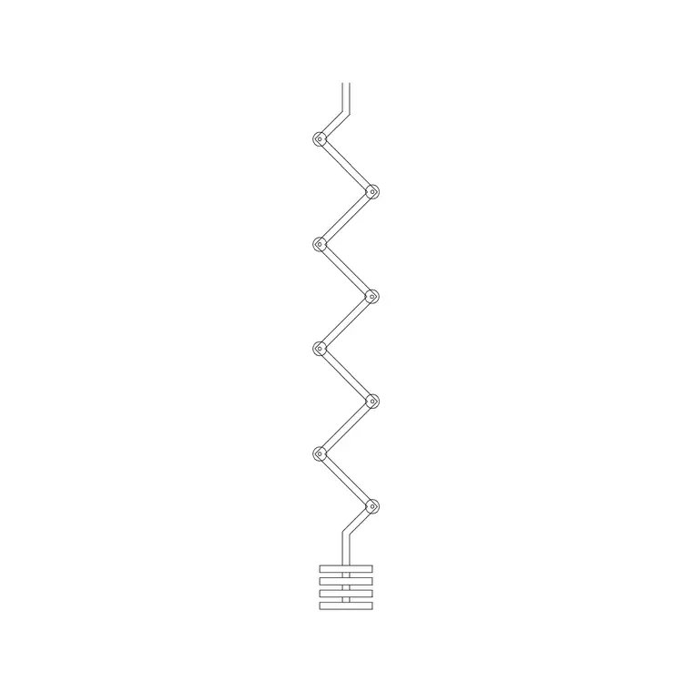
curtain and patient-bed-with-curtain, and the track height question
A privacy curtain track generally runs close to ceiling height in most ward layouts I have seen, high enough to clear a standing person's reach and give full floor-to-ceiling privacy when drawn, and while the exact figure is a project and ceiling-height specific decision rather than a fixed universal number, the practical habit is to note the intended track height on your elevation sheet rather than leaving it to be assumed from the plan.
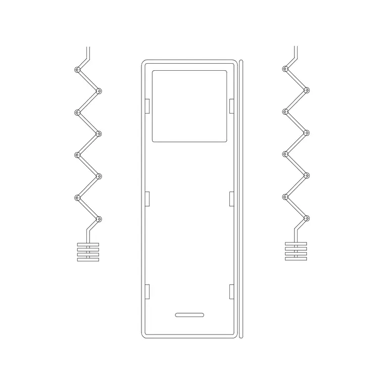
patient-bed-with-curtain bundles the bed and curtain in one insert for the standard case, and the standalone curtain block is what you fall back on for a bay that is not standard, a corner bed, an oddly angled room, or a bay pinched by a structural column, in which case redrawing the curtain run to match the actual geometry reads better on the printed sheet than stretching a pre-built shape to fit.
It is also worth remembering that the curtain's job changes slightly depending on where the bay sits relative to a window or an exterior wall, a bay against an outside wall sometimes needs the curtain track to wrap slightly differently to maintain privacy against a window view from outside, so a repeat unit that works perfectly for an internal bay does not always transfer without adjustment to the end bay of a ward that happens to sit against a window wall.
wash-basin-plan and wash-basin-elevation at each bay entrance
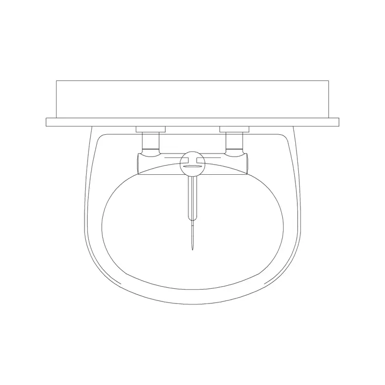
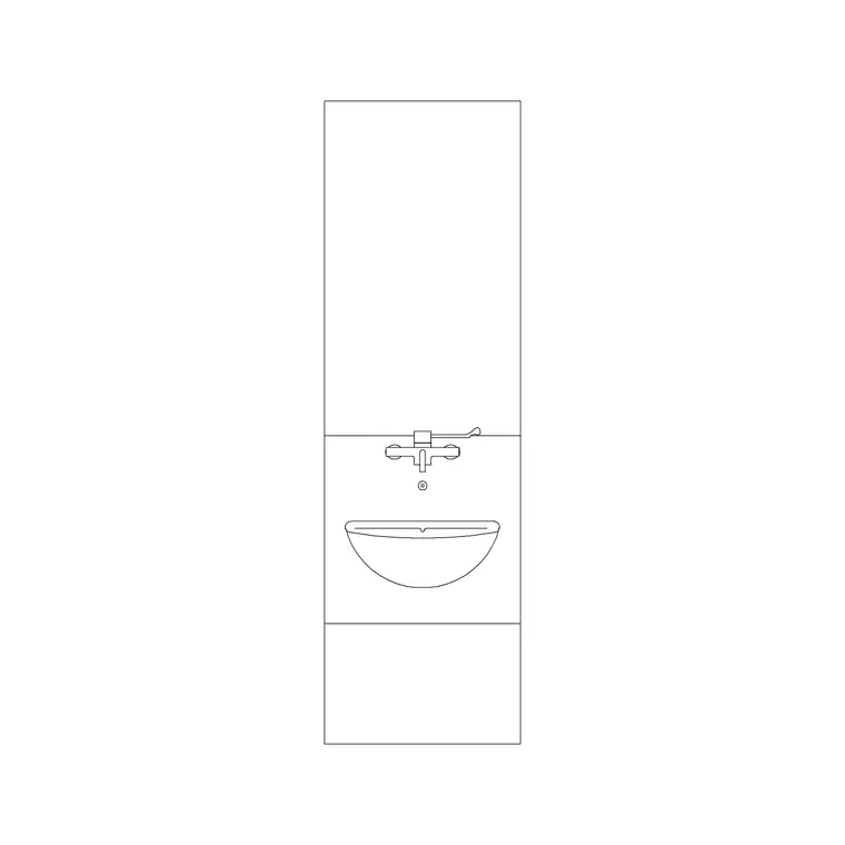
A basin near each bay entrance is close to a default expectation in ward planning guidance, driven by infection control practice as much as anything else, and wash-basin-plan paired with wash-basin-elevation lets you show the footprint against the wall and the height relationship to whatever sits above it in the same coordinated way we already used for the bed.
The sequencing habit worth building is placing the basin before you array the bay down the ward rather than after, because the basin position is usually what pins where the head wall service run has to stop and where the next bay's curtain track has to start, and catching a clash between the two early is a lot cheaper than discovering it after several bays are already copied down the room.
Beyond the basin itself, it is worth checking that the swing of the bay's own privacy curtain, once drawn fully open against the wall, does not end up sitting directly over the basin, which sounds like a minor overlap on paper but genuinely gets in the way of someone trying to use the basin while the curtain is pulled back for cleaning or bed-making, and this is exactly the kind of clash that only shows up once you draw the curtain in both its open and closed position rather than just the closed position most plans default to showing.
stand and trolley, and the clearance around the bedside
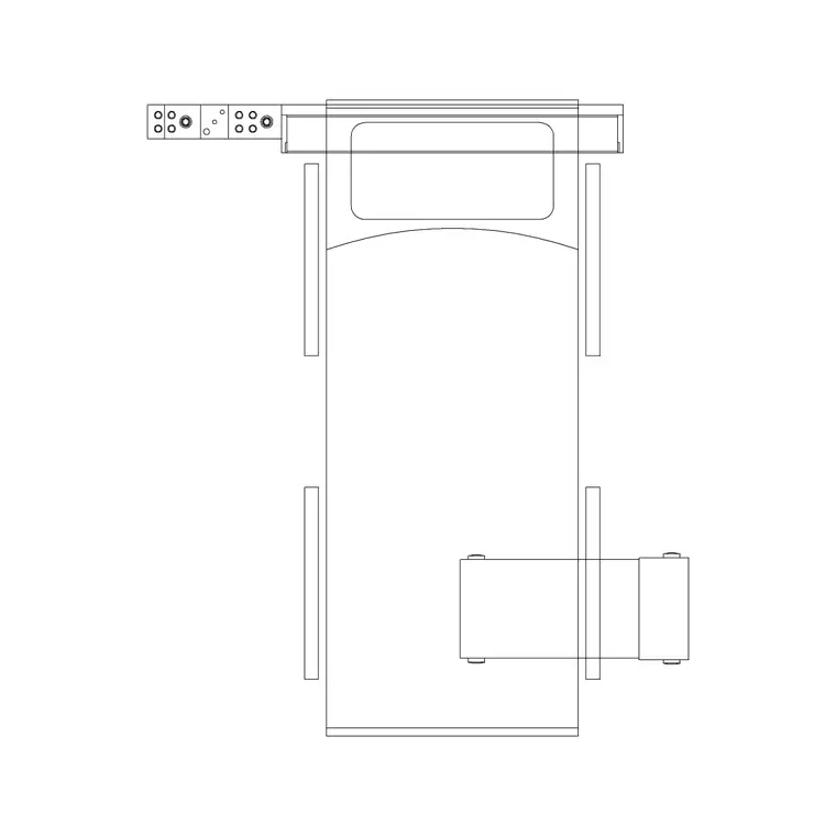
stand covers the mobile IV pole and similar bedside equipment, and trolley covers the mobile cart that nursing staff bring to the bedside for observations or medication rounds, and including both in even a schematic bay layout is what keeps a reviewer from assuming more open floor space exists around the bed than actually will once the room is in use.
The clearance question that matters most here is whether staff can move around at least a couple of sides of the bed without knocking into the stand, the trolley and the curtain track all at once, and this is exactly where an accessible bay, one designed for a wheelchair transfer or a hoist, needs noticeably more room than a standard one, so if your project has even one accessible bay in the ward, draw that one separately rather than assuming the standard bay dimensions will simply stretch to cover it.
A related point worth flagging honestly is that our medical set does not carry a dedicated hoist block, so if a project's accessible bay specifically needs to accommodate a mobile patient hoist, that piece of equipment is worth drawing as a simple labeled rectangle sized to the actual hoist footprint from whichever manufacturer the project has specified, rather than assuming one of our generic stand or trolley blocks stands in for it, because a hoist's swing and footprint genuinely differ enough from a simple IV stand that substituting one for the other in a clearance check would understate the real space needed.
Building the bay, and what this actually is
The order that has worked for me is head wall line first, bed on its fixed point, head unit next, curtain track sized to the real bay width, basin placed before arraying, then stand and trolley filled in around whatever space is left, and only then do I repeat the whole assembly down the ward, because arraying too early just means re-editing every copy the moment one earlier decision changes.
Worth being honest about to close this out, there is no single downloadable ward-bay DWG file that gets this right for every project, what exists is this set of blocks and the spacing logic in this post, and the actual bay dimensions still come from whatever space standard or code your specific project is drawing against, the blocks just give you a fast, consistent way to draw whatever that standard turns out to require.
One last habit worth adopting once a full ward's worth of bays is drawn is stepping back and checking the whole floor length against the room's actual dimensioned shell rather than trusting that the sum of your repeat units automatically lands where you expect, because a rounding error of even a small amount per bay adds up once multiplied across a dozen or more repeats, and catching that at the floor-plan stage is a great deal cheaper than catching it once the ward is being built out on site.
When to treat one bay differently from the rest
Not every bay on a ward floor should be drawn as a straight copy of the standard repeat unit, the end bay against a window wall, the bay next to the entrance door, and any bay designated as the accessible bay on the floor all tend to need their own specific check rather than inheriting the standard spacing automatically, and it is worth marking these bays clearly on the drawing early so a reviewer knows which ones were deliberately treated differently rather than assuming an inconsistency is a mistake.
The overall point of this post has been that the planning logic sitting behind these blocks, the repeat distance, the accessible bay allowance, the curtain and basin sequencing, matters more to whether a ward drawing survives review than which specific block variant you happened to pick, and that is really the honest takeaway here, the blocks are the vocabulary, the spacing decisions are the actual sentence.
Further reading
Questions
Frequently asked
Is there a single downloadable hospital ward layout file I can just drop in?+
No, we do not sell one pre-built ward DWG, what we have is the set of blocks in this post, patient-bed-with-curtain, bed-with-bed-head-unit, wash-basin-plan, curtain, stand and trolley, that you combine using your own project's spacing standard.
How much space should I actually leave between two bed bays?+
That number comes from your project's own space standard or local code rather than a fixed universal figure, the honest guidance is to add up the bed footprint, the curtain lane and the aisle clearance your standard requires rather than eyeballing a gap that just looks reasonable on screen.
Does the curtain block represent a fixed track length?+
No, it is a generic symbol you stretch, mirror or redefine to match whatever track run the actual bay geometry needs, the drawn shape is cosmetic as long as the track length matches what will really be installed.
Does an accessible bay for a wheelchair or hoist transfer need a different layout?+
Yes, an accessible bay generally needs meaningfully more clearance around the bed than a standard one, so treat it as its own drawing rather than assuming the standard bay dimensions will stretch to cover it.
Free downloads from this article

Free CAD block library
Download the blocks from this article — free, no signup