Matching a Paving Pattern CAD Block to a Real Paver Module
Why the paving pattern in your CAD block has to match a real paver's actual module size, and how to check before you specify.
Sumana KumarUpdated 11 July 20265 min read

The gap between a pretty pattern and a buildable one
A paving pattern CAD block will happily let you array a perfectly regular grid of pavers across any area you like, the software doesn't know or care whether that module actually corresponds to a paver product someone can buy, and that's exactly the gap that causes trouble later, a drawing that looks resolved on screen but turns into a change order once the contractor tries to source pavers at the module size the drawing implies and finds out the manufacturer's actual unit is a different size entirely.
Common real world paver module sizes worth knowing
Concrete pavers commonly come in module sizes somewhere around 100 by 200 mm for a standard brick format unit, up through larger format units in the 300 by 300 mm to 400 by 400 mm range for a more contemporary, fewer joint lines look, with thickness typically in the 40 to 60 mm range for pedestrian use and 60 to 80 mm or more for vehicle rated pavers. These are typical ranges across common manufacturers, not a fixed standard, and the actual figure always depends on the specific product line and region, so treat any number here as a starting point for a conversation with the actual supplier, not a spec you copy straight into a drawing.
It's also worth knowing that some paver systems are sold as multi size sets, three or four different module sizes meant to be laid together in a randomized pattern specifically to avoid the repetitive grid look a single module produces, and if a project is specifying one of these systems, a single repeating CAD pattern block genuinely can't represent it accurately, since the whole point of a multi size system is that the layout isn't a simple repeat. In that situation I'll either source or build a larger sample panel showing several metres of the actual randomized layout and then array that whole panel as one unit across the paved area, rather than trying to force a single small paver module block to stand in for a pattern that was never meant to repeat at a small scale in the first place.
Regional differences matter here too, module sizes and standard thicknesses common in one country's paver market don't always match another's, so if you're working from a supplier catalog outside your usual region, it's worth double checking the module figures rather than assuming a familiar number, like a 400 by 400 mm slab, is the standard everywhere, since a project relying on an imported or regionally sourced paver can easily end up with a module that doesn't match the domestic figures you're used to working with.
How to check a paving block's module before you commit to it
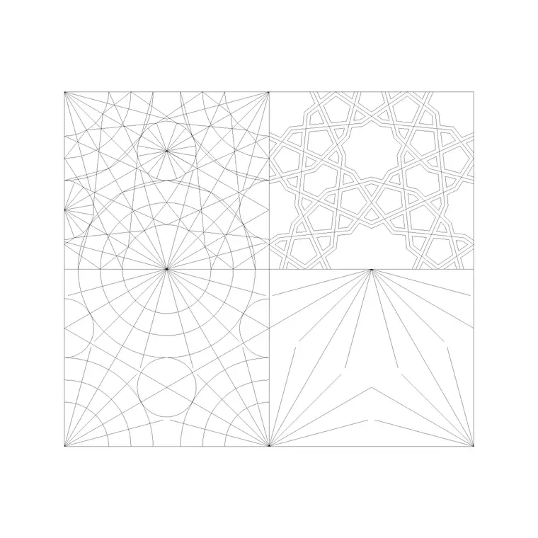
Before arraying any of the paving block patterns across a real project's driveway or patio, I'll draw a quick reference rectangle at the actual paver module the supplier has confirmed, then overlay it against the block's pattern to see if the joint spacing lines up, and if it doesn't, either pick a different pattern block whose module is closer, or if the pattern itself, herringbone, running bond, is right but the scale is off, rebuild just the module dimension while keeping the pattern logic, which is far less work than it sounds like once you're only adjusting one repeating unit rather than the whole array.
Why the module matters more on a driveway than a patio
On a patio, a module mismatch between the drawing and the real product is mostly a coordination annoyance, the contractor adjusts and the visual outcome is close enough. On a driveway, it's a bigger deal, because the interlocking pattern's structural performance under vehicle load is tied to the actual paver's dimensions and how the units key into each other, so a herringbone pattern drawn at the wrong module isn't just cosmetically off, it may not represent a laying bond the manufacturer actually validates for vehicle loading with that specific product, which is a real liability question, not just a drafting inconvenience.
Working the module into your drawing cleanly
Once you've confirmed the real module, set your paving block's array spacing to match exactly, joint width included, since paver joints typically run somewhere in the 3 to 10 mm range depending on product and installation method, and that joint width is part of what determines how many units actually fit across a given driveway or patio dimension. I keep a small reference note on the sheet, or in a detail callout, stating the actual paver product and module the pattern represents, so anyone picking up the drawing later, a contractor, a different drafter continuing the project, isn't left guessing whether the pattern shown is generic or tied to a specific specified product.
When it's fine to keep the pattern generic
Not every drawing needs the module locked down, early concept plans and presentation drawings for a client who hasn't selected a paver product yet are fine with a generic, representative pattern, that's actually the right level of resolution for that stage, since specifying an exact module before the product's chosen is putting the drawing ahead of the actual design decision. The module matching genuinely matters once you're moving into construction documentation, at the point where the drawing is meant to be buildable rather than illustrative, and that's the transition to watch for on any given project.
A worked example of checking a module before you commit
Say a client has selected a 300 by 300 mm concrete paver with a 6 mm joint for a driveway, and you're using one of the herringbone pattern blocks from the paving block set as your starting point. The check I'd actually run is to draw a single reference module, 306 mm square accounting for the joint, place it over the pattern block at true scale, and see whether the block's own repeating unit lines up with that 306 mm figure or whether it's built around a different, generic module instead. If it lines up, great, array away. If it doesn't, and it often won't exactly, because the block was likely built as a generic representative pattern rather than tied to one specific product, I'll either rebuild the module dimension while keeping the herringbone logic, which is usually just adjusting the array spacing parameters rather than redrawing the joint geometry from scratch, or I'll accept the generic module for an early concept drawing and flag it for correction once the drawing moves into construction documentation.
This kind of check takes ten minutes and it's the difference between a driveway pattern that's genuinely buildable at the module the client selected and one that just looks plausible until a contractor tries to actually set it out on site.
Further reading
Questions
Frequently asked
What paver module size should I use if the product hasn't been selected yet?+
For an early concept or presentation drawing, a generic, representative pattern is fine, no need to lock a module before the client has actually chosen a paver product. Match the pattern to the real module once you move into construction documentation.
Does joint width actually matter in the drawing?+
Yes, joint width, typically 3 to 10 mm depending on product, affects how many paver units fit across a given dimension, which matters for construction accuracy even though it looks like a minor detail on screen.
Why does module accuracy matter more for a driveway than a patio?+
A driveway pattern's interlock performance under vehicle load is tied to the real paver's actual dimensions. A module mismatch there isn't just cosmetic, it can mean the drawn pattern doesn't represent a laying bond the manufacturer has actually validated for vehicle use with that product.
Free downloads from this article



Free CAD block library
Download the blocks from this article — free, no signup