Laying Out a Modular Kitchen in AutoCAD with Free CAD Blocks
A working sequence for building a modular kitchen plan and elevation in AutoCAD using free DWG blocks, from cabinet run to finished scene.
Sumana KumarUpdated 19 July 202610 min read
What Modular Actually Means on a Drawing
Modular kitchen gets used loosely as a marketing term, but on an actual drawing it means something fairly specific, cabinetry and appliances built from standardized units and standardized widths rather than custom carpentry cut to fit one exact space. That standardization is exactly why free CAD blocks work so well for this kind of layout, a modular base cabinet, a modular wall cabinet and a standard appliance footprint are close enough to universal that a block drawn for one project genuinely transfers to the next one without much rework, unlike a bespoke joinery detail that really does need to be drawn from scratch every time.
This post walks through the sequence I actually use when laying out a modular kitchen from a blank plan, working from the cabinet run outward to appliances, ventilation and finally the elevation, using blocks from the kitchen category the whole way through. It is not the only valid order to work in, but it is the one that catches the most coordination problems early rather than late, which matters more than almost anything else when you are iterating a layout under a tight timeline.
One assumption worth stating plainly before starting, this sequence assumes a fairly standard residential kitchen footprint, an L-shape, a U-shape, or a single wall galley run, since those cover the overwhelming majority of modular kitchen projects that actually get built. An unusual island-heavy layout or a genuinely custom architectural kitchen will still benefit from the same underlying logic, work plan before elevation, lock the cabinet run before the appliances, but expect to spend more time on the plan stage specifically working out clearances that a standard layout would not need to think twice about.
Step One: Lock the Cabinet Run Before Anything Else
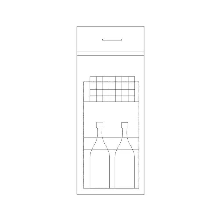
Everything in a modular kitchen gets positioned relative to the cabinet run, so that is where the layout has to start, not with appliances and not with the elevation. Using the standalone cabinet block alongside overhead-cabinet-elevation for the wall units above, rough in the base cabinet run along your longest available wall first, working in standard modular widths rather than stretching or compressing a run to awkwardly fit a leftover gap, since real modular cabinetry comes in fixed width increments and a layout that ignores that will not actually be buildable.
The reason this comes first is that every other decision, where the sink goes, where the range goes, how much clearance the fridge gets, depends on where the cabinet boundaries actually sit, and re-running that math after appliances are already placed wastes far more time than getting the cabinet run roughly right at the start. I usually block out the full run at a rough level, then come back and refine cabinet widths once the appliances are placed and I know exactly how much space each one is actually consuming.
A detail that trips up a lot of layouts at this stage, wall cabinet width does not have to match base cabinet width one to one along the run, and forcing that assumption produces a layout that looks rigid rather than considered. It is completely normal and often better for a wall cabinet run to skip a section entirely above a window or above the hob location, and using overhead-cabinet-elevation as a reference for how a professionally composed wall run actually breaks around those interruptions is more useful at this stage than trying to force uniform coverage across the entire wall.
Step Two: Drop In the Major Appliances at Plan View
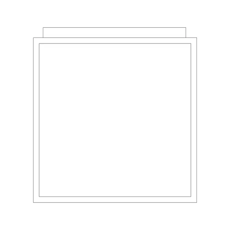
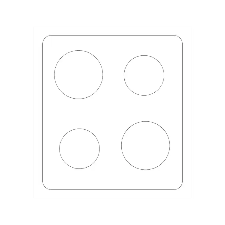
With the cabinet run roughed in, bring in refrigerator-plan-1 and cooking-range-plan-1 and position them within the run, refrigerator generally at one end where it can be accessed without crossing the main work path, cooking range roughly central or wherever the gas or induction supply point actually sits if that has already been determined by an engineer or a previous drawing. This is the step where the modular width increments actually get tested against reality, since an appliance footprint that does not divide cleanly into your cabinet module widths is going to force an awkward filler panel somewhere in the run.
It helps enormously to work in plan view for this step specifically rather than jumping straight to elevation, because plan is where clearance and circulation actually get evaluated, how much floor space sits between the range and the opposite counter, whether a cabinet door swing conflicts with an appliance door swing, whether two people could reasonably occupy the space at once. Elevation will tell you whether it looks right, but plan is what tells you whether it actually works, and skipping straight to elevation to save time here is one of the more common ways a modular layout ends up needing a rework later.
While you are working in plan, it is also the right moment to check appliance door swings against each other, a refrigerator door and a range hood control panel usually cause no conflict, but a dishwasher door and a nearby cabinet door both swinging into the same floor space definitely can, and this is exactly the kind of clash that is invisible on an elevation and completely obvious once you actually draw the door swing arcs on the plan. It takes a couple of minutes to add swing arcs for every hinged element on the counter run, and it is one of the cheapest checks in the entire workflow relative to how much rework it prevents.
Step Three: Ventilation Follows the Hob, Not the Other Way Around
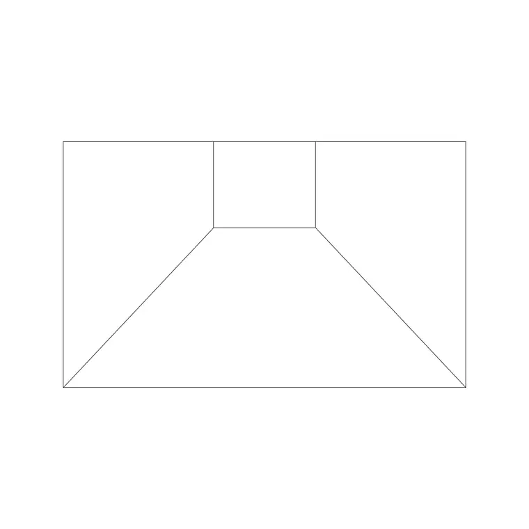
Once the cooking range is placed, bring in hood-plan-1 and center it directly over the hob rather than centering it on the cabinet run as a whole, since those two centerlines only match if the range itself happens to sit exactly in the middle of the run, which is genuinely not the common case in a modular kitchen built from standard width increments. Getting the hood centerline aligned to the actual cooking surface rather than to the wall or the cabinet boundary is a small check that is easy to skip and immediately obvious to anyone reviewing the plan once it is missed.
This is also the point in the sequence where duct routing, if the hood is ducted rather than recirculating, needs to at least be sketched conceptually, since the plan location of the hood determines where a duct run needs to travel to reach an exterior wall or a chase, and discovering late that the hood sits on the one wall without a viable duct path is exactly the kind of thing that is cheap to catch at this stage and expensive to catch after cabinetry has been ordered.
Hood width relative to hob width is worth a quick check too, a hood should generally extend at least as wide as the cooking surface beneath it and often a little wider, since a hood narrower than the burners it is meant to ventilate leaves the outer burners essentially unvented, which is a functional failure rather than a cosmetic one. If your cooking-range-plan-1 block represents a wider commercial-style range, double check that whichever hood-plan-1 sizing you are working from actually covers that width before locking the layout, rather than assuming a standard hood size will automatically be adequate.
Step Four: Build the Elevation From the Plan, Not Independently
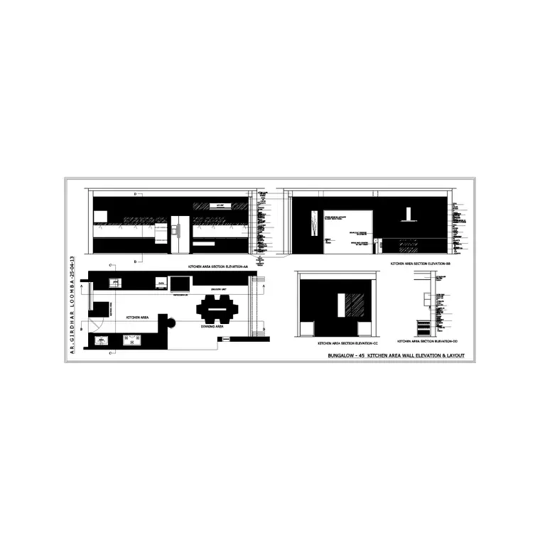
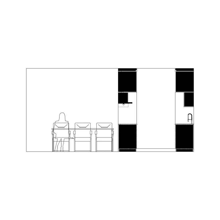
With the plan roughed in, cabinet run, major appliances and ventilation all reconciled against each other, move to building the elevation using kitchen-elevation or kitchen-and-dining-elevation as a starting composition, positioning cabinet, appliance and fixture blocks to match the widths and centerlines already established in plan rather than re-deciding those positions independently on the elevation sheet. This sounds obvious stated directly, but it is the single most common source of plan-to-elevation mismatch I see in student and early-career drawing sets, an elevation that was clearly built as its own composition without constant reference back to the plan dimensions.
The practical technique is keeping the plan visible in a separate viewport or a second monitor while building the elevation, and projecting key centerlines, the hob, the sink, the fridge edge, straight up from plan to elevation the way orthographic projection is actually meant to work, rather than eyeballing the elevation composition and hoping it happens to agree with the plan underneath it. Kitchen-and-dining-elevation is particularly useful here when the kitchen opens onto a dining area, since it shows the two spaces already resolved against each other rather than requiring you to work that transition out from scratch.
A specific check worth running every time at this stage, does the finished floor level shown on the elevation actually match the finished floor level assumed on the plan, and does the counter height, toe kick height and wall cabinet bottom height stay consistent across every segment of the run rather than drifting slightly between one cabinet block and the next. Small inconsistencies like a half-inch drift in counter height between two adjacent cabinet blocks pulled from slightly different sources are exactly the kind of thing that reads as sloppy on a printed sheet even though it would never be visible in the finished, physical kitchen.
Step Five: Use the Complete Kitchen Drawings as a Sanity Check
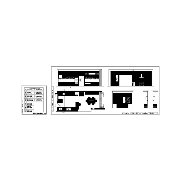
Once your own layout is roughed in on both plan and elevation, it is worth pulling up complete-kitchen-drawing-01 and complete-kitchen-drawing-02 not to copy them directly but to compare proportions, does your cabinet run height match a professionally composed reference, does the gap between your counter and your wall cabinets look reasonable next to a drawing that has already been through review. These two blocks function less as parts to insert and more as a finished answer key you can hold your own layout up against before calling it done.
This comparison step catches a specific category of error that is genuinely hard to catch by looking at your own drawing in isolation, proportion drift, where every individual dimension might technically be correct on paper but the overall composition still looks slightly off because of how those correct dimensions interact visually. A fresh reference drawing sitting right next to your own is often the fastest way to spot that kind of subtle mismatch, faster than re-checking every individual dimension against a spec sheet.
I also keep both complete kitchen drawings around specifically for client conversations that happen before a layout is finished, since showing a client a fully resolved reference scene early in a project, framed clearly as an example rather than their actual design, tends to produce much more useful feedback than asking them to react to a half-finished plan with placeholder blocks still sitting in it. People are generally better at reacting to something concrete than imagining a gap, and a finished reference drawing fills that gap productively during the early conversation stage of a project.
Common Mistakes and a Final Workflow Note
The mistakes that show up most often in modular kitchen layouts built from block libraries are all variations on the same root cause, working a view in isolation rather than constantly cross-checking it against the others. An elevation built without reference to the plan below it, a hood centered on the wrong axis, cabinet widths that do not sum to the actual wall length available, appliance clearances that look fine in elevation but fail in plan. Every one of these gets caught early by simply refusing to finish one view completely before starting to cross-check it against the next.
On the units and scale side, since a modular kitchen involves stacking many separately sourced blocks into one coordinated drawing, get your drawing units settled before you place a single block, and insert everything at a consistent scale factor from the start rather than fixing scale mismatches one block at a time after the fact. And once the plan and elevation genuinely agree with each other, the next real question, how the sink, hob and fridge actually relate to each other functionally rather than just geometrically, is exactly what the companion post on the kitchen triangle workflow in this series covers.
All of the blocks referenced through this whole sequence, cabinet, both complete kitchen drawings, both elevation composites, and every appliance plan block, download as free DWG files with no signup and are cleared for commercial use, so this entire workflow is genuinely runnable start to finish without hitting a paywall partway through a project, which is not something I could say about every block library I have used over the years, and it is a large part of why I keep coming back to this particular kitchen category for real client work rather than just for personal reference.
Further reading
Questions
Frequently asked
What does modular actually mean for a kitchen CAD layout?+
It means cabinetry and appliances built from standardized units and fixed width increments rather than custom carpentry, which is exactly why free block libraries work well here, a standard base cabinet block transfers cleanly between projects.
Should I start a modular kitchen layout from plan or elevation?+
Start from plan. Cabinet run, appliance clearances and circulation all get evaluated in plan view first, then the elevation gets built to match those already-resolved plan dimensions rather than being designed independently.
Why should the range hood align to the hob instead of the cabinet run?+
Because the hob rarely sits exactly centered within a modular cabinet run built from standard width increments. Centering the hood on the actual cooking surface rather than the wall or cabinet boundary is a small check that prevents an obvious visual mismatch.
How are the complete kitchen drawing blocks meant to be used?+
More as a reference than a template to copy directly. Comparing your own roughed-in layout's proportions against a professionally composed complete kitchen scene is a fast way to catch subtle proportion drift that is hard to spot by checking your own dimensions alone.
Free downloads from this article
Free CAD block library
Download the blocks from this article — free, no signup