Building a hospital ward layout from medical CAD blocks
A step by step approach to assembling a full hospital ward layout from downloaded medical CAD blocks, from bed grid to final sheet.
Sumana KumarUpdated 23 March 20265 min read
Starting from a block library instead of a blank sheet
Assembling a full ward layout from downloaded blocks is a genuinely different process from drafting one from scratch, and it took me a few projects to stop treating it like the same job done faster. When you're pulling patient beds, screens, seating and equipment from a library, the drafting effort shifts almost entirely away from drawing geometry and into decisions, spacing, numbering, and consistency across dozens of repeated inserts, and the ward layouts that come together cleanly are the ones where those decisions get made in a fixed order rather than improvised bay by bay.
Step one, set the grid before placing a single bed
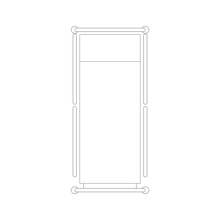
Before I insert a single patient bed plan block, I set a bay grid across the ward, a fixed module width that every bed bay repeats, based on the bed footprint plus circulation on both sides plus a bedside locker allowance, and I draw that grid as reference geometry on its own layer before any furniture goes in. Working this way means every bay is dimensionally identical from the start, rather than discovering three bays in that bay four is fifty millimetres tighter than the rest because it was placed by eye instead of against the grid. It's a slower first step and it pays for itself completely by the time you're forty beds into the ward.
I also build a small amount of tolerance into the grid module itself, typically rounding the bay width up rather than down to the nearest convenient figure, because a grid that's dimensioned to the exact minimum a bed and its clearances require leaves zero room for a later addition, a wider bariatric bed in one bay, or a piece of monitoring equipment that wasn't in the original brief, and that little bit of slack is far cheaper to build in at the grid stage than to find later by shaving clearance off every bay to squeeze one exception in.
Step two, place beds and check the plan against the elevation
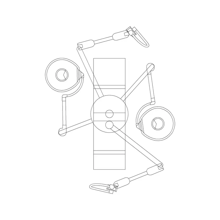
With the grid locked, I insert a patient bed plan block into every bay, keeping the insertion point consistent at the headboard corner across all of them, then bring in the elevation view against the headwall to check outlet and nurse call heights before the plan gets any further detail added. This is the point where I'd also bring in an ot-table-with-pendant block if the ward includes any high dependency bays with ceiling mounted services, checking pendant reach against the bed position in exactly the way I would in a full theatre, since HDU bays carry a lot of the same ceiling coordination problems as an OT on a smaller scale.
Step three, screens, seating and the circulation check
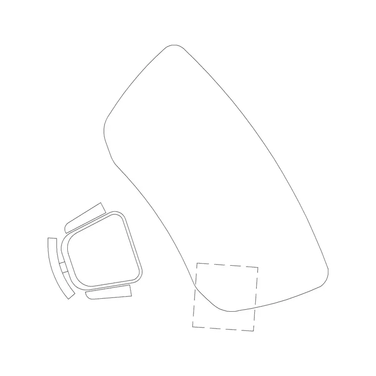
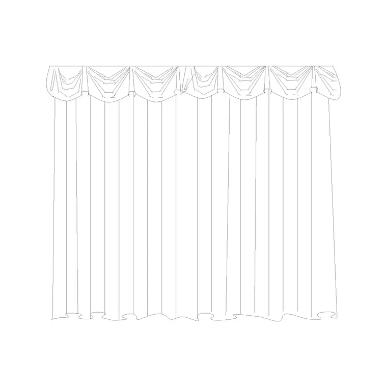
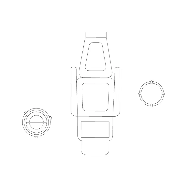
Once beds are placed and headwall coordination is confirmed, curtain or privacy screen blocks go around each bay next, tracked to wrap the bed on three sides while keeping the corridor side fully clear, and a recliner block goes in for visitor or attendant seating at each bay where the brief calls for it. With all of that in place, I run a circulation check the same way I would on any clinic layout, confirming a trolley or a bed on wheels can actually navigate the corridor and turn into each bay without clipping a screen track or a chair, which is the check most likely to surface a spacing mistake that's crept in through the earlier steps.
I also check the nurse station's sightlines into each bay at this stage, since a curtain track that fully encloses a bay for patient privacy can just as fully block a nurse's ability to observe a patient from the station, which matters most in higher acuity bays where visual monitoring between rounds is part of the care model. Where that's a genuine requirement, I'll note which bays need a viewing gap or a lower rail height built into the screening arrangement, rather than applying identical full enclosure across every bay regardless of the ward's actual observation needs.
Step four, numbering, tagging and the equipment schedule
With the physical layout holding up, every bay gets a number, and every block, bed, screen, recliner, gets a tag that ties back to a simple equipment schedule listing bay number, item, and any notes on specification. This step feels administrative compared to the layout work before it, but it's what makes the drawing usable by anyone other than the person who built it, a ward planner checking bed counts, a contractor pricing screens and seating, or a facilities manager tracking equipment years after handover, all of them lean on that numbering being consistent and complete.
Step five, getting it onto a sheet that reads properly
The final step is preparing the sheet itself, and a full ward at true scale rarely fits comfortably on anything smaller than an A1 sheet if you're working to ISO 216 paper sizes, sometimes split across two sheets with a match line if the ward is genuinely long. I keep every block un-exploded through this whole process specifically so the final sheet can adjust viewport scale without redrawing geometry, and if the practice is moving toward a building information modeling workflow for larger healthcare projects, this same bay by bay, grid first approach translates directly, since the sequencing discipline matters more than which software eventually renders the final sheet.
I also add a simple bay count and bed total directly on the sheet, tallied against the equipment schedule, since a ward planner reviewing the drawing wants that number immediately without having to count bays manually across a long sheet, and a mismatch between the tallied total and the actual bay count on the drawing is a fast, cheap way to catch a bay that got missed or double counted somewhere in the process before the drawing goes out for review.
What actually goes wrong when this order gets skipped
The ward layouts I've had to unpick and redo almost always skipped the grid step and went straight to placing beds by eye, which works fine for the first handful of bays and then compounds into a mess by the time spacing drift has accumulated across a long corridor. Numbering skipped until the end is the other repeat offender, since retrofitting tags onto forty beds after the fact takes longer than tagging them as you go, and it's far easier to make a mistake counting after the fact than while each block is fresh in front of you. Following the order, grid, beds and headwall, screens and seating, numbering, sheet, isn't the only way to build a ward layout, but it's the order that's consistently kept my drawings clean at scale.
Further reading
Questions
Frequently asked
What's the first thing I should draw when building a ward layout from blocks?+
Set a fixed bay grid across the ward before placing any beds, a repeating module width based on the bed footprint plus circulation and locker allowance, drawn as reference geometry so every bay is dimensionally consistent from the start rather than drifting bay by bay.
When should I add bay numbers and equipment tags to a ward drawing?+
As you go, right after each bed and its associated screen or seating are placed, rather than waiting until the layout is finished, since retrofitting numbers onto dozens of beds afterward takes longer and is more error prone than tagging each one while it's fresh.
What sheet size works for a full hospital ward layout?+
Most full wards need at least an A1 sheet at a workable scale, and a genuinely long ward may need splitting across two sheets with a match line, which is easier to manage if the blocks are kept un-exploded so viewport scale can adjust without redrawing anything.
Free downloads from this article
Free CAD block library
Download the blocks from this article — free, no signup