Garden Boundary Drawing from Fence and Gate CAD Blocks
A practical walkthrough for assembling a garden boundary drawing from fence and gate CAD blocks that line up cleanly on plan.
Saumyajit MaityUpdated 8 July 20265 min read
Starting from the property line, not from the blocks
The mistake I see most on a first pass at a boundary drawing is starting by dropping in a gate block, then a fence block, then trying to make the property line fit around whatever's already placed, when the order should genuinely run the other way, draw the actual property line and any required setbacks first, as a clean closed or open polyline pulled from your survey, and only then start populating fence and gate blocks along it, because a boundary drawing built around the property line will always coordinate correctly, while one built around the blocks tends to drift slightly off the real boundary the longer you work on it.
Choosing fence blocks for the different boundary conditions
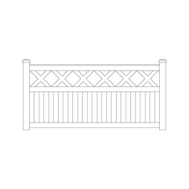
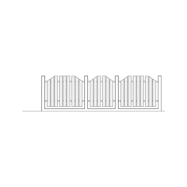
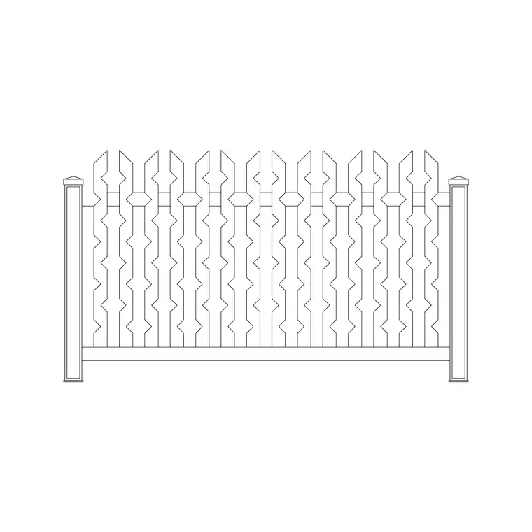
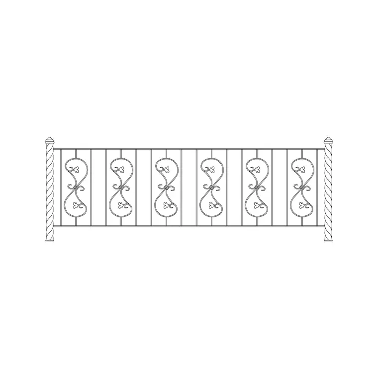
A single property boundary rarely wants one fence type end to end, front, side, and rear typically want different treatment. For a front boundary facing the street, fence design or one of the fence modern variants reads well and coordinates naturally with an entrance gate. For side boundaries shared with a neighbour, privacy matters more than style, so a taller, more solid fence design run, generally in the 1500 to 1800 mm range, is the more common call. For a rear boundary against open land or a shared amenity space, a lower or more open fence, sometimes even the iron fence block if sightlines out are wanted, can make more sense than a full privacy fence.
Placing the gate as the anchor point
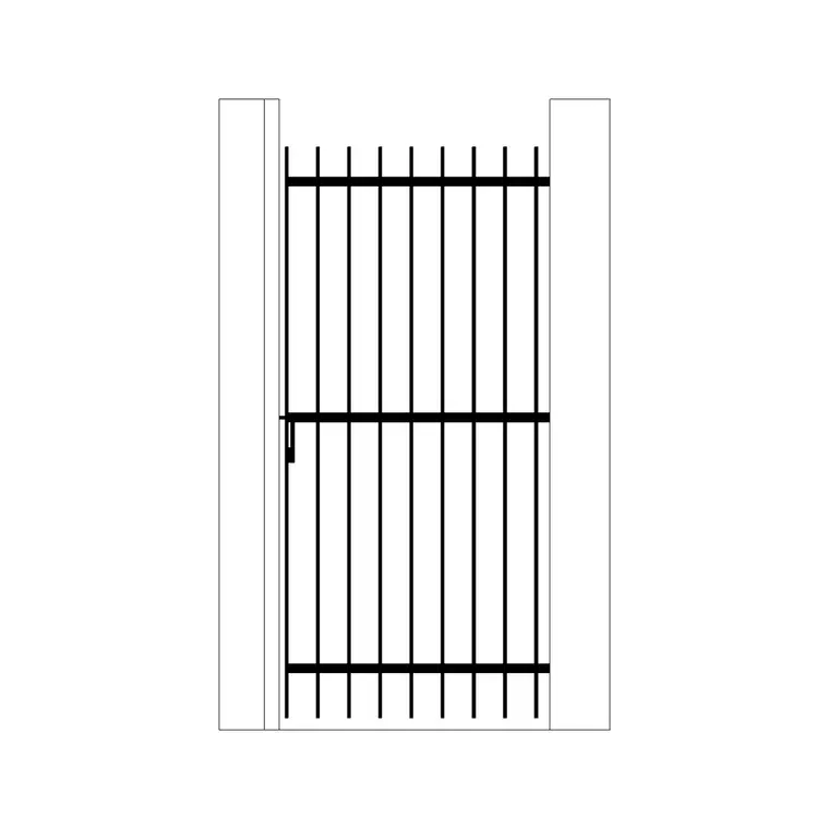
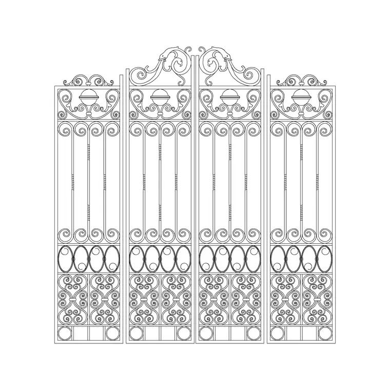
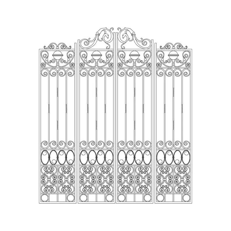
Once the fence runs are roughed in, the gate is really the anchor the rest of the boundary drawing organizes around, since it's both the visual focal point and the dimension that everything else measures off in a real construction set. Place the gate block first within its section of boundary, the iron gate, ornamented metal gate, or one of the metal gate double or metal gate single options depending on the brief, then trim or extend the adjoining fence runs to meet it cleanly at the gate posts or piers, rather than placing the fence run first and trying to cut a gate sized gap into it after the fact, which is where a lot of small dimensional errors creep in.
Keeping post and pier spacing consistent
A boundary drawing reads as professional or amateur largely based on whether the post or pier rhythm looks consistent along the run, and that's worth checking specifically once all the blocks are placed, since different fence blocks sourced from different points in the library can carry slightly different default post spacing, generally somewhere in the 1800 to 2400 mm range between posts depending on the fence style, and a visibly irregular spacing pattern, even if each individual block is drawn correctly, reads as sloppy the moment someone looks at the elevation as a whole rather than block by block.
Where the boundary run isn't a clean multiple of the block's default post spacing, and it rarely is on a real irregular site, I'll adjust the spacing slightly tighter or slightly looser across the whole run rather than fitting full spacing everywhere and leaving one oddly narrow or wide bay at the end, since an irregular last bay is exactly the kind of detail that draws the eye once you know to look for it, even though most people wouldn't consciously notice a slightly compressed rhythm across an entire run. This is a five minute adjustment once the boundary length is known, dividing the total run by a whole number of bays close to the default spacing and adjusting each bay slightly rather than leaving the math to fall wherever it happens to land.
The same logic applies at corners, where two boundary runs meet at an angle, I generally place a post or pier exactly at the corner point rather than letting a mid bay fall across it, both because a corner post reads as structurally correct and because it gives you a clean reference point to measure both adjoining runs from, rather than each run's spacing being set independently and potentially landing awkwardly close together right at the corner.
Layer discipline across a mixed boundary drawing
With this many different block types on one boundary, fence, gate, sometimes a wall or planting bed mixed in, layer discipline is what keeps the drawing usable rather than a tangle you can't isolate later. I keep fence, gate, and any wall elements on their own distinct layers even when they're visually part of one continuous boundary run, so I can turn the gate off to check fence continuity, or isolate just the gate and pier elements for a detail sheet, without hunting through a merged layer to find what I need.
Bringing plan and elevation together
A complete boundary drawing generally needs both a plan view, for the site plan showing the boundary's actual path and gate location, and an elevation, for a presentation or a construction detail showing height and material, and where the site's blocks come as matched pairs, the iron gate plan and iron gate elevation for instance, use both rather than approximating one from the other, since a hand derived elevation from a plan view tends to drift in proportion in a way a purpose drawn matched pair doesn't.
Common review comments on boundary drawings and how to avoid them
A handful of review comments show up again and again on boundary drawings, and most of them are avoidable with a quick self check before submission rather than something a reviewer genuinely needs to catch for you. The most common is a gate swing shown without checking clearance against the adjacent fence run or an obstruction just inside the boundary, a bin store, a meter box, something that was added late and never checked against the gate arc. Another is inconsistent fence height called out in the elevation versus what's actually dimensioned on the plan, which happens when the two views get updated separately during revisions and one gets missed. A third is a gate or fence block placed slightly off the actual surveyed property line because it was eyeballed into position rather than snapped to the boundary polyline.
Running a specific pass for just these three things, gate clearance, plan and elevation height consistency, and boundary line accuracy, before calling a boundary drawing finished catches the majority of comments I've seen come back from a review, and it takes a fraction of the time that responding to and correcting those comments after submission would.
Further reading
Questions
Frequently asked
Should I place the gate or the fence run first?+
Rough in the fence runs against the property line first, but treat the gate as the anchor point once you're refining dimensions, placing it fully within its section of boundary and trimming the adjoining fence to meet it, rather than cutting a gate gap into an already finished fence run.
What post spacing should I use along a fence run?+
Typically somewhere in the 1800 to 2400 mm range between posts depending on the fence style, though the exact figure depends on the specific product and any wind or structural requirements for the actual project.
Do I need both a plan and an elevation for the boundary?+
For most projects, yes, a plan view for the site plan and gate location, and an elevation for material, height, and presentation. Use matched plan and elevation pairs where the block library provides them rather than deriving one view from the other by eye.
Free downloads from this article
Free CAD block library
Download the blocks from this article — free, no signup