Car Turning Circle and Swept-Path Templates Explained
What turning circle and swept path templates actually mean, typical vehicle turning ranges, and how to trace one using real CAD vehicle blocks.
Sumana KumarUpdated 15 April 202611 min read
Turning circle: kerb to kerb, or wall to wall
When someone quotes you a car's turning circle, they're almost always talking about one of two related but different numbers: the kerb to kerb diameter, which is the circle traced by the outer front tire as the driver turns the wheel to full lock, and the wall to wall diameter, which adds a bit more to account for the overhang of the car's front corner, the bumper and wing mirror, as it swings past a wall or parked vehicle. For drafting purposes on a site plan, wall to wall is the safer number to design around, because it's the one that actually determines whether a car clips a wall, a bollard or the corner of a building as it turns, rather than just where the tire itself tracks.
Manufacturers publish these figures because they matter for real world usability, and depending on the exact model, kerb to kerb turning circle for an ordinary passenger car typically falls somewhere in the 10 to 12 meter range, with the wall to wall figure usually landing a meter or so above that. Compact cars and small hatchbacks tend to sit toward the tighter end of that range, while larger sedans, SUVs and anything with a longer wheelbase pushes toward the wider end, sometimes considerably beyond it for full size SUVs and vans.
Typical ranges by vehicle class
- Small hatchback or compact car: often in the 9.5 to 10.5 meter kerb to kerb range, tight enough to make a U turn comfortably on an ordinary two lane road - Mid size sedan: usually somewhere around 10.5 to 11.5 meters - Large sedan or crossover: commonly 11 to 12.5 meters - Full size SUV or van: frequently 12 to 13.5 meters or more, and can be considerably wider depending on the wheelbase
These are general ranges pulled from how manufacturers typically describe turning circle across vehicle classes, not a fixed universal constant, and the actual figure for any specific model can sit outside these bands. When a project genuinely depends on the number, a tight underground ramp junction, for instance, always confirm against the manufacturer's published spec for the vehicle class actually expected to use the site, rather than a rule of thumb.
Articulated vehicles and anything towing a trailer sit outside this whole comparison, since a trailer doesn't follow the towing vehicle's turning circle at all, it tracks its own path determined by the trailer's own axle position and hitch length. Any site expecting trailers or articulated delivery vehicles needs a completely separate swept path model rather than an adapted car or van figure, since applying a passenger vehicle's turning circle to a towed load will understate the space actually required, sometimes considerably.
How the number is actually measured
It's worth understanding broadly how a turning circle figure gets generated before you rely on it. Manufacturers typically measure it by driving the vehicle at full steering lock around a level, dry surface and recording the diameter of the circle traced by the outer front wheel, which is why it's often called the kerb to kerb figure. Because this is measured under close to ideal conditions, flat surface, low speed, tyres and steering in good condition, real world performance on an uneven site surface or in tight, low speed maneuvering can differ slightly from the published number, which is one more reason to treat it as a design reference rather than a guaranteed minimum you can design right up against.
Swept path versus turning circle
A turning circle tells you the tightest circle a vehicle can complete at full steering lock, which is useful shorthand, but it assumes the vehicle is turning through a full continuous circle, and most real maneuvers on a site, entering a driveway, turning into a loading bay, negotiating a junction corner, are partial turns through an irregular path, not a full circle. That's what a swept path diagram actually models: the full envelope traced by every part of the vehicle, front overhang, rear overhang, and the wider path the rear wheels cut inside the front wheels' path, as it follows a specific, real turning movement rather than an idealized circle.
This is the diagram you actually want when checking whether a specific vehicle can get around a specific corner on a specific site, because a turning circle number alone can't tell you whether the rear corner of a long wheelbase van will clip a kerb on the inside of a tight bend, something a swept path trace catches immediately because it plots the rear overhang's path explicitly rather than leaving it to guesswork.
Off-tracking: why the rear wheels always cut the corner
Off-tracking is the term worth knowing if you want to talk about swept path with any precision, and it describes something you can actually see happen every time you watch a bus or a truck negotiate a tight corner: the rear wheels never follow the same path as the front wheels, they always track a shorter, tighter line to the inside of the turn. The longer the wheelbase, and the tighter the turn, the more pronounced this off-tracking becomes, which is why a long wheelbase van or a truck with a trailer can look like it's about to clear a corner with the front of the vehicle and then drag the rear corner or the trailer's own rear axle straight across a kerb that the driver never even saw coming.
For an ordinary passenger car this effect is small enough that most drafters can safely ignore it and just check the outer swept envelope as described above, but it becomes the dominant factor the moment you're checking anything with a genuinely long wheelbase or a towed trailer, since a trailer's own axle sits behind its own separate pivot point at the hitch, and it cuts an even tighter line than the towing vehicle's own rear wheels do. This is exactly why a rule that works fine for cars, add a bit of margin around the vehicle's swept path and call it done, quietly stops being safe the moment a site brief mentions an articulated delivery vehicle, and it's worth flagging that distinction early in a project rather than assuming a general margin covers every vehicle type that might eventually use the same route.
Steering lock and wheelbase, not just overall length
Two things drive turning circle far more than overall vehicle length: wheelbase, the distance between front and rear axles, and steering lock, how far the front wheels can turn. A longer wheelbase generally means a wider turning circle for the same steering lock, which is why vans and larger SUVs often need noticeably more room to turn than their overall length alone would suggest. Steering lock varies by vehicle too, and it's part of why two cars of similar size can have meaningfully different turning circles, so total vehicle length is a rough proxy at best, not a reliable stand in for turning performance.
This is also why two vehicles that share a similar wheelbase can still turn differently in practice, since the actual steering linkage geometry connecting the two front wheels, commonly referred to as Ackermann geometry, determines how each wheel's individual turn angle relates to the other, and manufacturers tune this differently across models even at a broadly similar size and wheelbase.
Building a simple check in AutoCAD
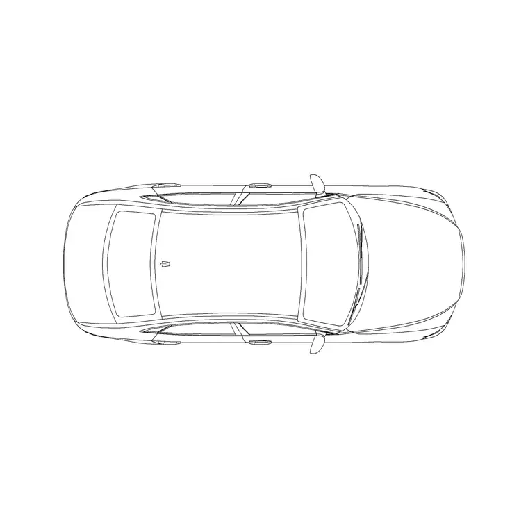
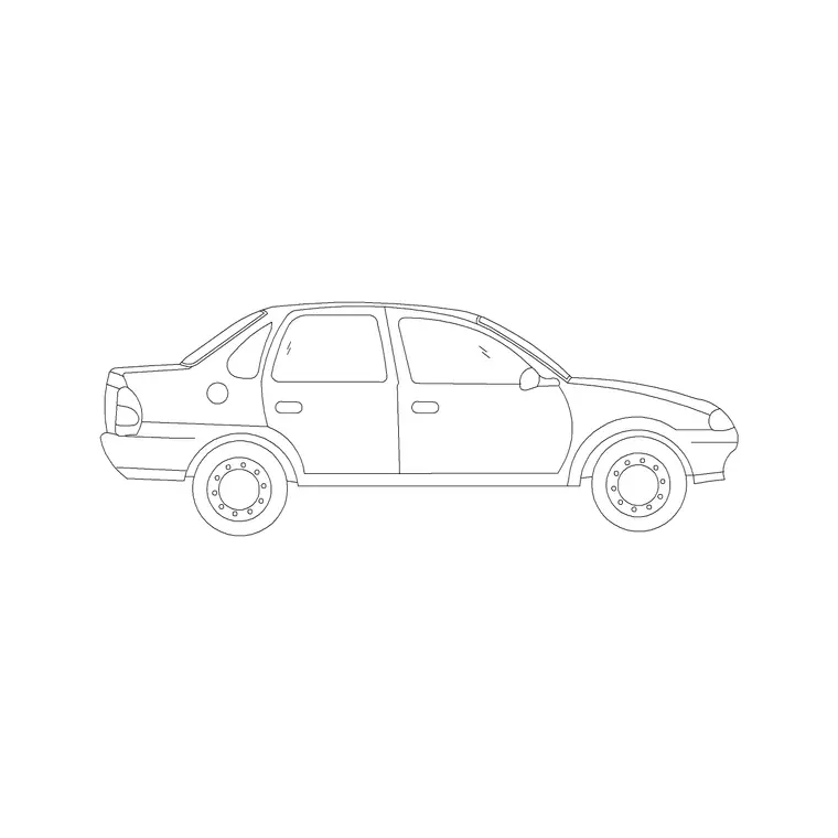
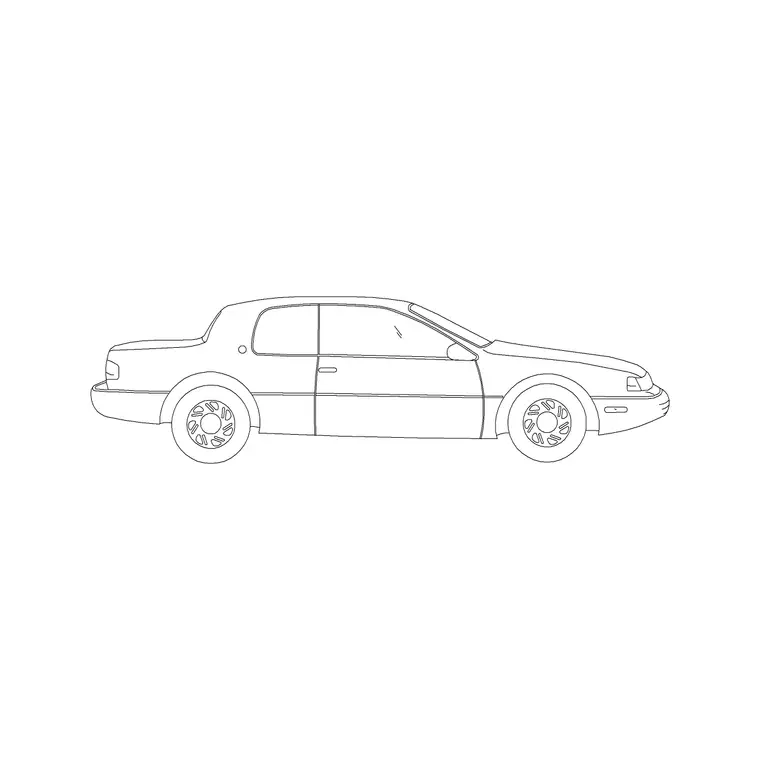
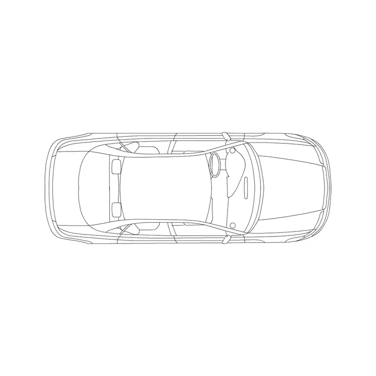
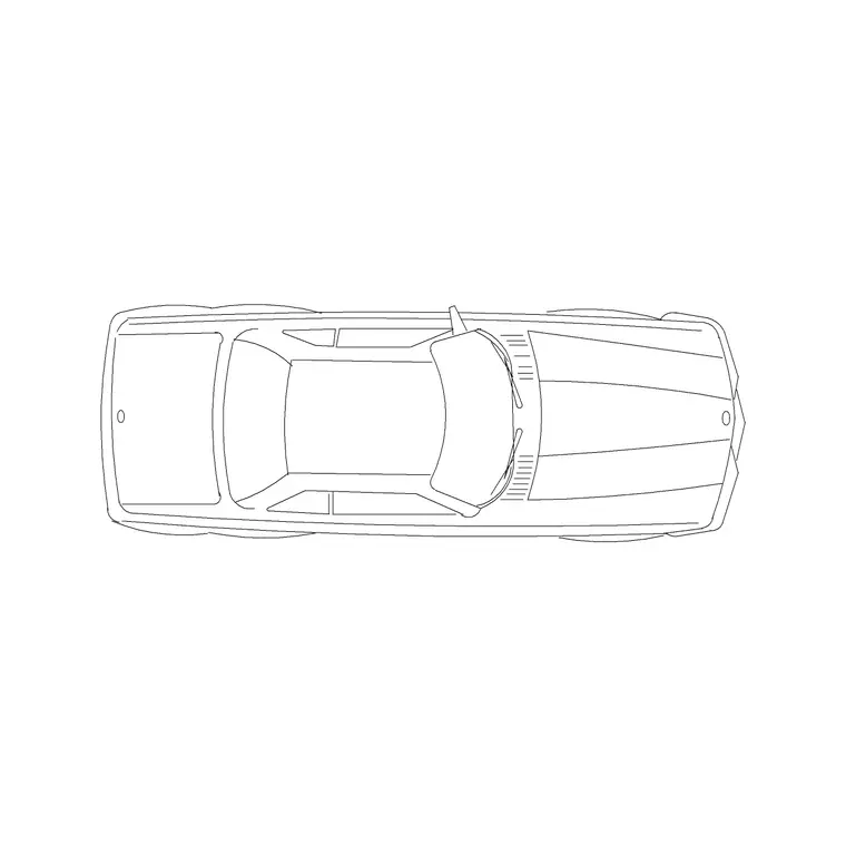
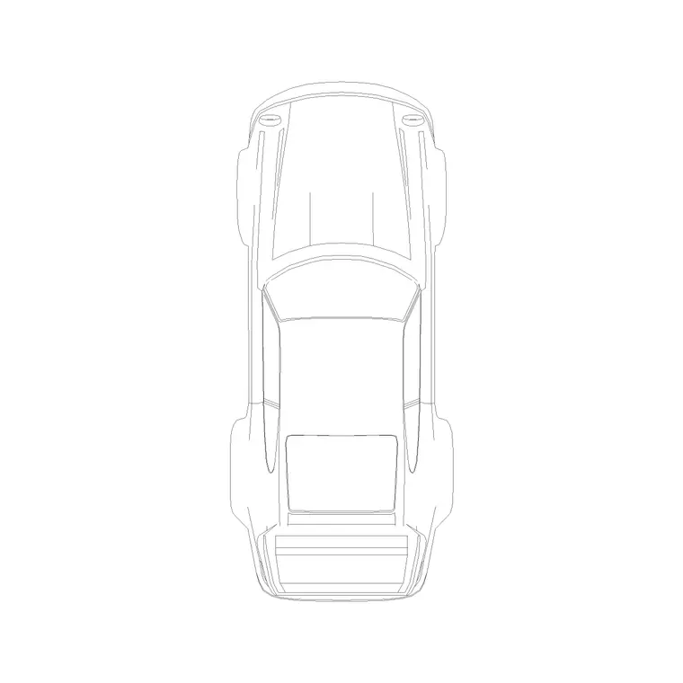
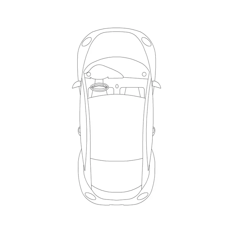
The most practical way to sanity check a tight turn on your own drawing is to work from a real vehicle footprint rather than a generic template circle drawn from memory. Insert one of our plan view vehicle blocks, car-plan-1 or car-plan-2 for an ordinary sedan reference, or suv-car-plan-7 if the site genuinely needs to accommodate a larger vehicle, then rotate and copy it at several points along the turning path you're checking, tracing the front and rear overhang corners as you go. Doing this by eye at three or four positions along a corner, entry, mid turn, exit, will expose a clash with a kerb or column far faster than trying to calculate a theoretical arc, because you're checking against the actual footprint rather than an assumption about it.
A practical way to do this without redrawing the same block repeatedly is to insert one copy of the plan view block, then use rotate with the copy option, or a polar array where the turn is close to uniform, to lay down a handful of positions along the path in a single operation. Sketch a rough centerline for the intended turning path first, even just a simple arc or spline, then place copies of the vehicle block with a consistent reference point, typically the center of the rear axle, snapped onto that centerline at intervals, rotating each copy to follow the centerline's direction at that point. This gives you a fast visual trace of the vehicle's swept envelope without modeling continuous motion, and it takes only a few minutes once you've done it a couple of times.
For anything genuinely safety critical, a fire access route, a loading dock a delivery truck must reverse into, dedicated swept path software that models continuous vehicle paths is the professional tool for the job, and this manual block based check should be treated as an early stage sanity check during design development, not a substitute for that verification on anything where a wrong answer has real consequences.
Here's roughly how that looks in practice on an actual corner, say a 90 degree turn off a site access road into a loading yard that's tighter than you'd like. Start by drawing the centerline of the intended path as a simple two point arc through the corner, roughly matching where you expect the driver to actually steer rather than the theoretical shortest line. Insert the vehicle plan block at the start of that arc with its rear axle reference point snapped to the centerline, then copy and rotate it to four or five stations along the arc, entry, quarter point, midpoint, three quarter point, exit, each time rotating the block so its own centerline matches the tangent direction of the path centerline at that station. Once you've got those four or five silhouettes laid down, look specifically at the rear outside corner of the vehicle body at each station, since that's the point that swings widest on the inside of a turn and the one most likely to clip a kerb or a column that the front of the car cleared cleanly a moment earlier. If any of those rear corner positions overlaps an obstruction on your drawing, you've found your problem station, and it's usually cheaper to nudge the corner radius or pull the obstruction back a few hundred millimeters at that specific station than to redesign the whole junction.
When the calculated turning path still doesn't fit
Sometimes a corner or turning space genuinely can't accommodate a single, continuous turning movement for the vehicle in question, and in those cases the practical answer on a real site is often a multi point turn rather than redesigning the whole layout around an oversized single sweep. If your site plan is going to rely on a driver completing a shunt, a forward move followed by a reverse correction, to get around a tight corner, it's worth showing that clearly in the design documentation rather than leaving it implied, since a reviewer checking against a single pass swept path template will flag it as a failure when it might actually be an acceptable, deliberately designed multi point movement for a low frequency maneuver.
Where swept path checks matter most on a site
Swept path checks earn their keep at a handful of predictable pinch points: the corner where a site access road meets the public road, any point where a driveway narrows near a gate or wall, loading bays where a larger delivery vehicle has to reverse in a straight line after a turn, and basement or multi storey car park ramps where a tight helical turn compounds with a gradient change. Anywhere two of these constraints stack, a narrow turn on a ramp, for instance, is worth an early swept path check well before the design is locked in, because retrofitting extra turning room after the structure or the boundary wall is built is rarely an option.
It's also worth identifying the largest vehicle that will use a route regularly, not just the smallest one that technically satisfies day to day use. A residential development's everyday traffic might be ordinary cars, but the same route still needs to work for the removal van on moving day and the refuse collection vehicle every week, and those larger, less frequent vehicles are often the real governing case for a corner's geometry even though they're not the vehicles parked in the layout most of the time.
Pitfalls worth checking twice
- Using a passenger car's turning circle to size a route that will actually see delivery vans or larger vehicles - Forgetting rear overhang, which swings wider than most people expect on longer wheelbase vehicles, particularly on the inside of a turn - Checking only the ideal line through a corner rather than a driver who arrives off center and has to correct - Assuming a published turning circle figure already includes mirrors and bumper overhang, when it may only reflect the tire path - Sizing a route around the everyday visitor car while forgetting the weekly refuse vehicle or the occasional removal van that also has to use it
A turning circle number is a useful first filter, but the swept path check against a real vehicle footprint, run at the actual pinch points on your site, is what tells you whether the design genuinely works rather than just looking plausible on paper.
Further reading
Questions
Frequently asked
What's the difference between a turning circle and a swept path?+
Turning circle is a single number describing the tightest full circle a vehicle can complete at full steering lock; a swept path is a diagram tracing the full envelope a specific vehicle occupies through an actual, often partial, turning movement on your site.
What's a typical car turning circle?+
Most ordinary passenger cars fall somewhere in the 10 to 12 meter kerb to kerb range, with compact cars toward the tighter end and larger SUVs and vans toward the wider end or beyond it.
Can I do a swept path check with your CAD blocks?+
You can do a useful early stage sanity check by tracing our plan view vehicle blocks through a turn by eye at a few points, but for anything safety critical, dedicated swept path software modeling continuous vehicle movement is the right tool.
Does wheelbase or overall length matter more for turning circle?+
Wheelbase matters more. A longer wheelbase generally needs a wider turning circle at a given steering lock, which is why vans and larger SUVs often turn wider than their overall length alone would suggest.
Free downloads from this article
Free CAD block library
Download the blocks from this article — free, no signup