Recliner chair CAD blocks: plan and elevation views compared
Why a recliner looks nothing alike in plan versus elevation, what's in the CADBlockDWG recliner block, and how to use both views without clearance mistakes.
Saumyajit MaityUpdated 9 June 20266 min read
The first time a client questioned a recliner block
I had a client once stare at a furnished floor plan and ask why the recliner in the corner of the family room looked like a plain rounded rectangle when the mood board photo showed this big, structured wingback thing with a footrest kicked out. That question comes up more than you'd think, and the honest answer is that a plan view and an elevation view of the same recliner are drawing two completely different things, right, one is the footprint from directly overhead and the other is the silhouette from the front or side, and a recliner is one of the few furniture pieces where those two shapes genuinely don't resemble each other because the mechanism changes the object's outline depending on whether it's upright or reclined.
That's the whole reason this post exists. Recliner CAD blocks trip up drafters not because the geometry is hard but because people insert the wrong view into the wrong sheet, or they don't realise the footprint block is already drawn at the reclined extent, so I want to walk through what's actually in a recliner block, how to read each view correctly, and where the clearance mistakes happen.
What's in the recliner block on CADBlockDWG
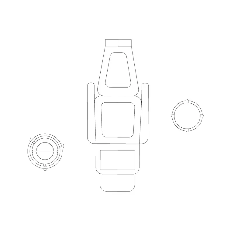
The recliner block on the site sits in the medical category rather than general furniture, which makes sense once you think about where recliners show up as a specified item rather than a decorative pick, clinic waiting rooms, infusion suites, dental recovery bays, assisted living lounges, and home healthcare setups all spec a recliner by name because the reclining mechanism itself matters clinically, not just aesthetically. The block ships as a top view, which is the plan representation you drop straight into a floor plan, and it's available in both DWG and DXF so it opens cleanly whether you're in AutoCAD or a DXF reading package.
What you're downloading is clean, real scale geometry on sensible layers, no proxy objects, no weird nested blocks that explode into a mess when you try to edit one line. That matters more than it sounds like it should, because a recliner's outline has curves at the arms and a stepped edge where the footrest section meets the seat, and sloppy geometry there is exactly the kind of thing that looks fine zoomed out and terrible the moment you zoom in to trim a wall around it.
Reading the plan view without guessing the footprint
Here's the part people get wrong most often, the plan view of a recliner block is usually drawn to represent the chair's functional footprint, which for a lot of recliner blocks means accounting for some amount of footrest extension rather than showing the chair fully closed up like a normal armchair. Residential recliners in the closed position typically run somewhere in the range of 700 to 950 millimetres wide and around 900 to 1000 millimetres deep, but once the footrest is out that depth can extend out toward 1600 to 1900 millimetres depending on the model, and clinical recliners used in infusion or dialysis settings often sit even larger because they're built for a caregiver to work around the patient.
So before you drop the block into a room and start measuring clearance off it, actually check what state the footprint represents. If the block you've inserted is the compact closed footprint, you still need to mentally reserve the extended zone in front of it for when someone actually reclines, otherwise you'll draw a layout that looks generous on paper and turns out cramped the first time someone kicks the footrest out.
Reading the elevation view without misreading the mechanism
An elevation, by contrast, is showing you the chair's silhouette from the front or the side, and this is where you actually see the backrest angle, the headrest height, and the arm height that the plan view can't communicate at all. Armrest height on a recliner typically lands somewhere around 550 to 650 millimetres off the floor, and overall back height, measured to the top of the headrest, is commonly in the range of 1000 to 1100 millimetres for a standard recliner, taller for a wingback style. That's the information you actually need for an interior elevation sheet, a rendering reference, or a millwork drawing where you're checking that a recliner's headrest doesn't collide with a window sill or a shelf above it.
The side elevation is also the view that tells you how far the backrest swings when it goes fully reclined, which is a completely different number from the footrest extension you'd read off a plan. A recliner that reclines to close to horizontal can push the top of the backrest back by several hundred millimetres, and if there's a wall directly behind the chair, that's the dimension that decides whether the mechanism can actually operate at all.
Combining both views on one sheet without conflicts
What I actually do when a project needs both the plan and the elevation is keep them as separate block insertions on separate layers, never trying to force one drawing to do both jobs. The plan block goes into the floor plan layer, scaled and rotated to match the room, and the elevation block goes onto an interior elevation or furniture schedule sheet where it's referenced against a wall section. Keep them tagged with a consistent naming convention, something like FURN-RECLINER-PLAN and FURN-RECLINER-ELEV, so anyone opening the file later isn't stuck guessing which insertion is which.
It's also worth double checking scale the moment you insert either block, because a block inserted at the wrong scale factor is the single most common reason a recliner suddenly looks three metres wide on a plan. Use a known reference dimension, like the armrest height or the closed footprint width mentioned above, and measure the inserted block against it before you trust the layout.
Where drafters actually lose clearance
The mistakes I see most often come down to three things. First, treating the plan footprint as fixed when it should account for the reclined extension, which quietly eats the walking clearance you thought you had in a small den or a clinic bay. Second, grabbing the elevation block and scaling it down to drop into a plan, which distorts proportions because elevation and plan views are not interchangeable just because they're both a 2D drawing of the same object. Third, and this one's specific to clinical settings, forgetting that a recliner in a treatment bay needs clearance on both sides for a caregiver or equipment cart, not just clearance in front for the footrest.
At the end of the day, a recliner is a mechanism as much as it's a piece of furniture, and drawing it accurately means respecting that the plan and elevation are answering two different questions, footprint and silhouette, and neither one alone gives you the full picture of how the chair behaves in use.
Further reading
Questions
Frequently asked
Does the recliner plan view show the chair open or closed?+
Check the block before you rely on it, but most recliner plan blocks on the site represent the functional footprint, which usually accounts for at least partial footrest extension rather than the fully closed silhouette. Always reserve extra depth in front of the chair for full recline.
What formats does the recliner CAD block come in?+
It's available as a DWG and a DXF, drawn as a top view, so it drops straight into an AutoCAD floor plan or any DXF compatible package without a conversion step.
How much wall clearance does a recliner need behind it?+
It depends on the model, but a fully reclined backrest can push back several hundred millimetres from its upright position, so leave a healthy gap between the chair back and any wall, and check the side elevation view rather than guessing off the plan alone.
Free downloads from this article
Free CAD block library
Download the blocks from this article — free, no signup