Kerb Types and Dropped-Kerb Details Explained
Common kerb profiles, typical upstand heights and dropped kerb detailing for vehicle crossovers and pedestrian access, with real CAD blocks for context.
Sumana KumarUpdated 20 June 202611 min read

What a kerb actually does on a site plan
A kerb does three jobs on a site plan that are easy to take for granted until one of them is missing: it physically restrains the edge of a paved or planted area so it doesn't erode or get driven over, it manages a level change between two surfaces, a road and a footpath, typically, and it visually guides both drivers and pedestrians toward where they're meant to be, a continuous kerb line reads as this is the edge of the carriageway without needing a sign to say so. On a drawing, a kerb is usually a simple linear detail, but its profile, height and where it breaks, for a dropped crossover, for instance, carries real functional meaning that's worth getting right rather than treating as a decorative line.
It's also one of the cheaper, more permanent decisions on a site plan, once a kerb line is set out and the units are laid, moving it later usually means breaking out and relaying a length of finished road or paving, which is a meaningfully bigger job than adjusting a line on a drawing. That's a reasonable argument for spending a bit more time getting the kerb layout right at design stage rather than treating it as a detail to sort out once the more visible elements of the site are settled.
Common kerb profiles
Kerb profiles generally fall into a small number of recognizable families. An upstand or half battered kerb has a visible vertical or steeply angled face and is the most common type separating a road from a footpath, giving a clear physical and visual edge. A flush kerb sits level, or very close to level, with the adjacent surface, and is typically used where a level, unobstructed transition is wanted, most often at a dropped crossing or a shared surface street where the distinction between vehicle and pedestrian space is intentionally blurred. Bullnose and splayed profiles round or angle the top edge for a gentler transition, often used where cyclists or wheelchair users cross regularly even where a full drop isn't specified.
A half battered profile specifically refers to a kerb face angled rather than perfectly vertical, which is a genuinely practical detail rather than a purely aesthetic one: the angled face is more forgiving of a vehicle wheel that clips it slightly while parking or turning, deflecting the tyre rather than catching it the way a fully vertical face can, which is part of why it's such a common default choice for ordinary roads rather than the exception.
Typical upstand heights
Upstand kerb height is typically specified somewhere in the range of 100 to 150mm above the adjacent carriageway, enough to be a clear physical and visual edge without becoming a significant trip or mounting hazard where pedestrians need to step across it occasionally. The exact figure depends on the specific standard your project is designed to and the road classification involved, so treat this as a general range to sanity check a drawing against, not a number to specify without confirming your local standard first.
Kerb materials, and edge restraint away from vehicle routes
Kerb units are typically supplied as precast concrete, natural stone such as granite, or formed in situ as a continuous poured strip, and the choice affects more than just appearance on your drawing. Precast concrete units come in standard lengths and a limited set of standard profiles, which usually makes detailing straightforward since you're really just specifying a known product from a manufacturer's range. Natural stone kerbs, granite being the common example in a lot of markets, are more often specified for their durability and appearance on a higher profile scheme, and because they're typically cut to length on site rather than supplied in a single fixed module, the detail drawing needs to communicate the intended joint spacing rather than relying on a standard unit length. In situ poured kerbs are more flexible for a curved or non standard alignment but need their own formwork and curing detail called out separately from the paving either side of them.
Not every kerb like edge on a site plan is actually a vehicle kerb. A lower, purely decorative or restraint edging is commonly used around a planting bed or a gravel path with no intention of ever taking a vehicle load, and it's worth distinguishing these clearly on your drawing, both in the callout and often in the drawn profile itself, since specifying a full vehicle rated kerb section purely for a planting bed edge is an unnecessary cost, while specifying a lightweight edging restraint where a vehicle will actually cross it is a genuine failure waiting to happen.
Joint width and pattern is worth specifying explicitly on any natural stone kerb detail too, since granite units cut to length on site can otherwise end up with inconsistent joint gaps that read poorly on a finished frontage even though the kerb itself performs its structural job perfectly well. A typical approach is to specify a maximum joint width, often a small handful of millimeters, along with a bedding and jointing mortar specification, so the contractor has a clear target rather than cutting units to whatever length is convenient on the day and packing the gaps afterward.
Dropped kerb and vehicle crossover detailing
A dropped kerb, sometimes called a vehicle crossover, is a length of kerb lowered to, or close to, footpath level specifically to let a vehicle cross a footpath onto a driveway or site access without the front or rear overhang scraping on the way over. The transition either side of the dropped section is usually eased with a short splayed or ramped run rather than dropping abruptly, both to protect the vehicle's underside and to keep the footpath itself walkable across the dip rather than presenting pedestrians with a sudden step. Crossover width is typically sized to the vehicle types expected to use it, a single domestic driveway crossover is usually narrower than a commercial site entrance built to take delivery vehicles, and this is exactly the kind of dimension worth checking against a real vehicle plan block rather than a rule of thumb width.
The transition units either side of a dropped section are commonly supplied as quadrant or splayed end units specifically shaped to taper from the full upstand height down to the flush dropped section, rather than being cut or improvised from standard straight kerb lengths on site. Specifying these correctly on your drawing, rather than just drawing a dropped section and leaving the transition detail to the contractor, is what actually gets you a clean, properly formed crossover rather than an ad hoc looking patch.
A worked example: detailing a driveway crossover on a tight urban frontage
Say you're detailing a single driveway crossover on a narrow urban frontage, a townhouse plot where the footpath itself is only a couple of meters wide and the kerb line runs close to a street tree pit a few meters to one side. Start by confirming the crossover width against the actual vehicle expected, an ordinary family car in this case, using a vehicle plan block dropped over your drawn crossover to check the swept path clears both the splayed transition units and the street tree pit's protective root zone, since a crossover positioned too close to a tree pit can end up needing a redesign specifically to protect the tree's roots from being compacted by that pit anyway. Draw the transition quadrant units explicitly rather than just showing a dropped section with a note, since on a narrow frontage like this the transition length itself eats into a meaningful share of the available kerb run, and it's worth checking that the full transition, upstand to flush to upstand again, physically fits within the plot's own frontage width before assuming a standard transition length will simply work.
Where the footpath is this narrow, it's also worth checking that the dropped section, even at its flush low point, still leaves the footpath's own running width wide enough for two pedestrians to pass each other, since a crossover that drops the kerb but also encroaches on the footpath's paved width solves one problem while creating another. This is exactly the kind of detail that looks fine on a small scale site plan and turns out to be uncomfortably tight the moment it's checked at full scale against the footpath's actual paved dimension.
Dropped kerb for pedestrian access
The other major use of a dropped kerb has nothing to do with vehicles at all: dropping a kerb to near flush level at a pedestrian crossing point is a core accessibility detail, letting a wheelchair, pushchair or mobility scooter cross a road or car park route without a step. These crossings are almost always paired with tactile paving, a textured surface, often blister pattern at a controlled crossing, to warn a visually impaired pedestrian that they're approaching a vehicle route, and the gradient of the ramp down to the dropped section is typically kept gentle, broadly in line with general accessible ramp guidance, since a steep transition defeats the purpose of dropping the kerb in the first place. The Wikipedia entries on universal design and accessibility are useful general background reading on why this detail is treated as a baseline requirement rather than an optional nicety in most modern guidance.
Width matters here too, and it's a detail that's easy to under specify: a dropped crossing needs to be wide enough for two wheelchair users, or a wheelchair user and a pedestrian with a pushchair, to pass each other comfortably, not just wide enough for a single person to cross in isolation. On a busy pedestrian route, a narrow dropped crossing becomes a genuine pinch point at peak times even though it technically satisfies a minimum width requirement on paper.
Radius kerbs at corners and junctions
Where a kerb line turns a corner, at a junction or the entrance to a site, the corner is usually rounded rather than left as a sharp right angle, and the radius chosen needs to accommodate the swept path of the largest vehicle expected to turn through that corner, not just look tidy in plan. A radius that's comfortable for a passenger car can be genuinely too tight for a delivery van or a larger vehicle, which is one more reason a swept path sanity check is worth doing at exactly these corner points before the kerb line is finalized.
It's also worth checking a corner radius against more than just the obvious delivery van, right, refuse and recycling collection vehicles are a weekly reality for almost every site and often have a wider turning circle and less forgiving overhang than people initially assume when they size a corner purely around the vehicles a client happens to mention during design meetings.
Drawing kerb lines against real paving and vehicle blocks
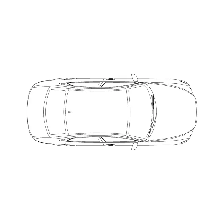
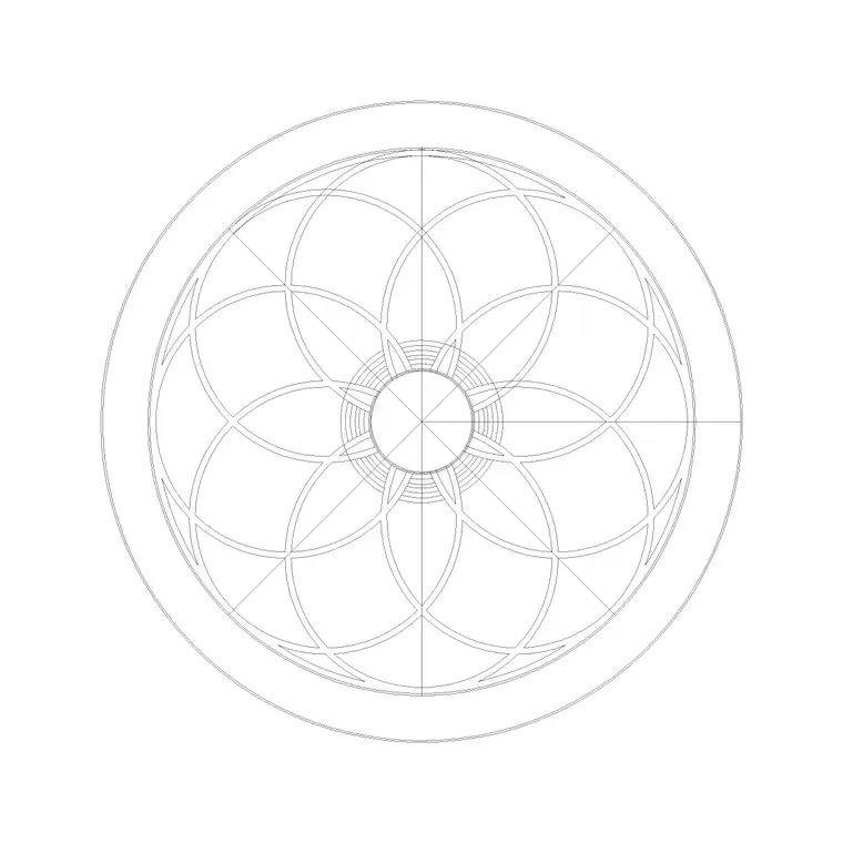
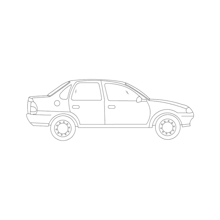
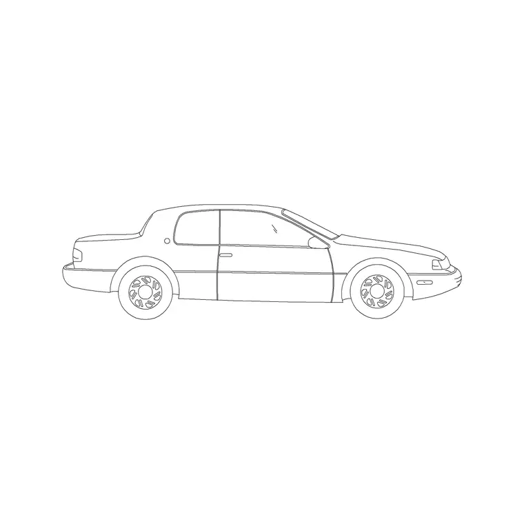
Once you've set your kerb lines and dropped crossover widths, it's worth placing one of our vehicle blocks, the compact sedan car or the 2 door sedan car, directly over the crossover in plan to visually confirm the vehicle footprint actually clears the kerb radius and crossover width you've drawn, rather than trusting the dimension alone. For the paved surface either side of the kerb line, our paving blocks, paving-block-1, paving-block-3 or paving-block-4, are a straightforward way to represent the finished surface and check that a paving module lines up sensibly against the kerb line rather than being cut awkwardly at the edge.
This same check is worth repeating at both the widest and narrowest points of a crossover, not just the middle, since a splayed transition means the usable width genuinely changes along its length, and a vehicle footprint that clears comfortably at the crossover's centre can still catch a corner nearer the splayed end where the kerb line is actively curving back toward full upstand height.
Common mistakes
- Specifying a single standard upstand height without checking whether the specific road classification calls for something different - Dropping a kerb crossover to the right width for a car but too narrow for the actual delivery or refuse vehicle that will use it - Forgetting tactile paving at a pedestrian dropped kerb, or specifying it without checking the current accessibility guidance for pattern and extent - Rounding a corner kerb radius by eye rather than checking it against the swept path of the largest vehicle expected to use that corner - Specifying a full vehicle rated kerb profile purely for a planting bed edge where no vehicle load was ever intended - Detailing a dropped crossover without specifying the transition or quadrant units either side, leaving a rough, improvised looking joint on site - Sizing a dropped pedestrian crossing for a single wheelchair user rather than checking it against two people passing each other at a busy time of day
Most of these come down to the same root cause, treating a kerb line as a fixed, generic detail rather than checking it against the specific vehicles, pedestrians and gradients your own site actually has to accommodate.
Further reading
Questions
Frequently asked
What's the difference between an upstand kerb and a flush kerb?+
An upstand kerb has a visible vertical or angled face, typically 100 to 150mm high, and is the standard edge between a road and footpath. A flush kerb sits level with the adjacent surface and is used where a stepless transition is wanted, like a dropped crossing.
How wide should a dropped kerb crossover be?+
It depends on the vehicles expected to use it. A domestic driveway crossover is typically narrower than a commercial entrance sized for delivery vehicles, so check the crossover width against a real vehicle footprint for your specific use case.
Why is tactile paving used with dropped kerbs?+
Tactile paving, usually a blister pattern at a controlled crossing, warns a visually impaired pedestrian that they're approaching a vehicle route, and it's a standard pairing with dropped kerbs in most current accessibility guidance.
Do you have kerb CAD blocks?+
We don't currently carry a dedicated kerb profile block in the library. Our paving blocks are useful for representing the adjacent finished surface, and our vehicle blocks help check crossover widths and corner radii against a real footprint.
Free downloads from this article

Free CAD block library
Download the blocks from this article — free, no signup