First Angle vs Third Angle Projection Explained
How first angle and third angle orthographic projection differ, which regions use which, and how to keep views consistent on a sheet.
Saumyajit MaityUpdated 3 July 202610 min read
Why one convention mix-up causes real construction errors
I've seen a single reversed projection convention turn a perfectly good elevation into a mirror image of what the building actually looks like, and the frustrating part is that nothing about the geometry was wrong, only the arrangement of views around the plan was flipped from what the reader expected. First angle and third angle projection are both completely valid ways of laying out orthographic views, and most of the world's confusion about them isn't a drafting skill problem, it's a convention problem, two systems solving the same problem in a mirrored way, used by different regions, sometimes clashing inside the same multinational project.
The reason this keeps catching experienced drafters, not just beginners, is that both conventions produce drawings that look internally consistent and perfectly professional on their own terms, there's no error message, no obviously wrong geometry, just a plan and a set of elevations arranged the way one system expects and read by someone trained on the other. A contractor reading a first angle set as though it were third angle won't necessarily notice anything is off until they try to reconcile an elevation against the actual site condition and the two don't match up the way they expect.
This is genuinely one of the older conventions in technical drawing, the underlying logic goes back to descriptive geometry long before CAD existed, and the reason it's stuck around in two competing regional flavours rather than converging into one global default is mostly historical inertia, national drafting standards were established independently, and once a few generations of engineers and architects trained under one system, changing it wholesale was never worth the disruption. So the practical reality today is that both conventions are permanently here to stay, and the skill worth building is fluency in recognising and switching between them, not waiting for the world to standardise on one.
What orthographic projection actually is
Orthographic projection, at its core, is the technique of representing a three dimensional object as a set of flat, two dimensional views, typically a plan, a front elevation, a side elevation and sometimes a section, each one looking straight at the object from a perpendicular direction so there's no perspective distortion to measure against. Every CAD drawing you've ever produced that shows a plan next to an elevation is using orthographic projection whether or not anyone in the office ever says the word out loud, and it's the reason a drawing can be measured accurately with a scale rule instead of being a picture that only looks right from one viewpoint.
The part that needs a convention is how those separate views get arranged relative to each other on the sheet, because the object itself doesn't dictate that, a human decision does, and that's exactly where first angle and third angle split.
It helps to separate two things that get bundled together in people's heads, the actual content of a view, what a from above look at a roof shows, what a front elevation shows, is entirely determined by the geometry and doesn't change between the two systems, it's purely the placement of that view relative to the others on the sheet that the convention governs. So learning to read both isn't really learning two different ways of drawing, it's learning two different filing systems for the exact same set of views.
First angle projection: the logic and where it's the default
In first angle projection you imagine the object sitting between the observer and the projection plane, so the view you see gets projected through the object and lands on the far side, which has the practical effect that the view placed above the plan is actually looking at the object from below, and the view placed to the right of the front view is actually looking from the left. It sounds backwards until you get used to reading it, but the underlying rule is simple, each view is placed on the opposite side from where the observer is standing. First angle projection is the default across most of Europe, India and a large share of Asia and Africa, and if you're drafting to Indian Standard conventions or most European national standards, first angle is what's assumed unless a drawing explicitly says otherwise.
A useful mental trick for reading first angle sets is to remember that the arrangement is genuinely counter-intuitive on purpose, so resist the urge to interpret the layout the way you naturally would, the view below the plan is actually the one looking up from underneath, and once that clicks, the whole set reads consistently rather than fighting your intuition sheet after sheet.
For anyone trained on Indian architectural or engineering coursework specifically, first angle usually isn't something you had to consciously decide to adopt, it's simply the default every textbook and every teacher assumed from the start, which is exactly why the convention feels invisible until the day you're handed a set drafted the other way and the arrangement suddenly looks wrong even though nothing about it actually is.
Third angle projection: the logic and where it's the default
Third angle projection places the object behind the projection plane instead, so the view you see is the one that lands closest to the observer's actual viewpoint, meaning the view above the plan is the one looking down from above, and the view to the right of the front view is genuinely looking from the right. This is the more intuitive one for most people encountering projection for the first time, because the arrangement matches where you'd naturally expect to stand to get that view, and it's the standard convention across the United States, Canada and a number of other countries that historically follow ANSI drafting conventions.
Because third angle matches intuition so closely, it's also the convention most CAD software tutorials and default template libraries quietly assume when they show you an example layout, which is fine if you're working in a third angle market but worth double checking if you've picked up a habit from a tutorial and are now drafting for a first angle client without realising the mismatch. It's also the convention most likely to appear in generic stock templates, tutorial videos, and default settings baked into commercial CAD software regardless of where that software is actually being sold, simply because third angle happens to be the historical convention of the country where most mainstream CAD software was originally developed.
The projection symbol: how to tell which one a drawing uses
Because the two systems produce genuinely different view arrangements from the same object, every properly drafted set should carry a small projection symbol somewhere near the title block, usually a truncated cone or a pair of circles shown in both projections, that tells the reader which system is in use without them having to guess from context. It's a tiny detail on the sheet, easy to skip when you're setting up a template in a hurry, but it's the fastest way for anyone picking up an unfamiliar drawing set to confirm whether the elevation above the plan is a from above view or a from below view before they start taking measurements off it.
If a drawing set doesn't carry the symbol at all, the practical fallback is to check whichever regional standard the rest of the project documentation follows, because an unlabeled drawing from an Indian consultancy is first angle by default, and an unlabeled one from a US based firm is third angle by default, in the overwhelming majority of cases.
The symbol itself is small enough that it's easy to treat as decorative rather than functional, but on a set that's going to be handed to a fabricator, a structural checker, or a contractor who's never met the design team, it's genuinely doing load bearing communication work, and leaving it off a template because nobody remembers what it means defeats the entire point of having a universal convention in the first place.
Setting up view arrangement correctly either way
Getting this right in AutoCAD isn't really about a special tool, it's about being deliberate with where you place each generated or manually drafted view relative to the plan, because the software has no built in concept of first or third angle, it just places whatever you tell it to place where you tell it to place it. Decide the convention before you start laying out viewports, place your front elevation, then consciously place the top view either above for third angle, or effectively treat the arrangement as projecting through the object with the corresponding side views mirrored to match for first angle, and keep every sheet in the set consistent, because a set that switches convention halfway through is far more dangerous than a set that's simply drafted in the less common one, since at least a consistently applied convention can be corrected with one blanket instruction.
When you're generating views automatically from a 3D model rather than drafting each one by hand, most software defaults to one convention out of the box, usually third angle, so it's worth explicitly checking that setting the very first time you set up projected views on a new template rather than assuming it matches whatever your last project happened to use. Once it's set correctly at the template level, every subsequent view you generate off that template inherits the right arrangement automatically, which is a far more reliable habit than manually checking each individual view after the fact.
Where this trips up mixed international teams
The place this actually costs time and money is on a genuinely international project, a design team in one country handing a base model to a fabricator or a contractor in another, because if nobody explicitly states the projection convention, someone downstream will assume their own local default and read the elevations backwards, and by the time that's caught it might already be sitting inside a shop drawing, or worse, cut material. So basically, the fix costs nothing, state the convention in words on the title sheet, add the projection symbol, and don't assume everyone on the distribution list trained under the same drafting standard you did.
A related, smaller version of the same problem shows up whenever a firm merges drawings from two consultants who trained under different regional standards, a structural engineer's shop drawings arriving as an xref into an architect's third angle base file, drafted first angle out of habit, and unless someone flags it explicitly during coordination, the mismatch tends to survive right up until someone lines the two sets up against each other and the elevations simply don't agree. It's a five minute conversation to prevent and a genuinely time consuming one to untangle after the fact, which is exactly the kind of asymmetry worth respecting early.
A quick checklist for verifying an unfamiliar drawing set
When a set lands on your desk from outside your own office and you need to move fast without guessing wrong, a short verification pass is worth the two minutes it takes:
- Look for the projection symbol near the title block first, before reading any individual view - If there's no symbol, check the country or standard the consultant's title block references - Confirm the arrangement makes sense by comparing one obviously asymmetric feature, a door swing, a sloped roof, against where it appears in two adjacent views - Flag the convention explicitly in your own coordination notes before basing any new work off the set, rather than assuming it matches your own default
Further reading
Questions
Frequently asked
Which projection convention does most of the world actually use?+
First angle is the default across Europe, India and much of Asia and Africa, while third angle is the standard in the United States and Canada, so the correct one depends entirely on which regional standard the project follows.
How can I tell which projection a drawing uses if there's no symbol?+
Check the origin of the drafting standard or the country the consultant is based in as a fallback, but the safest approach is always to look for the projection symbol near the title block, or simply ask rather than assume.
Does the projection convention change the actual dimensions on a drawing?+
No, the measured dimensions and geometry are identical either way, only the arrangement of which view sits where relative to the plan changes, so it never affects accuracy, only how the sheet should be read.
Do I need different CAD blocks for first angle versus third angle drawings?+
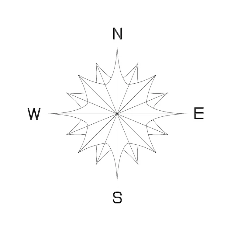
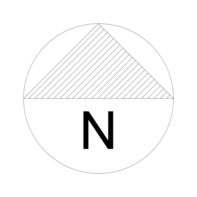
No, blocks like doors, windows or a north arrow are drawn as plan or elevation views and drop into either convention without modification, it's the sheet layout and view arrangement around them that changes, not the blocks themselves.
Free downloads from this article
Free CAD block library
Download the blocks from this article — free, no signup