ISO vs ANSI vs JIS Drawing Sheet Sizes Compared
A clear comparison of ISO A-series, ANSI, and JIS sheet sizes for CAD drawings, with practical guidance on choosing and setting one up.
Sumana KumarUpdated 26 April 202610 min read

Why sheet size is the first decision, not the last
I've opened enough inherited drawing files to notice a pattern, the ones that are painful to print, painful to hand off and painful to revise all skipped the same first step, which is deciding the sheet size before anything else got drawn. Sheet size isn't cosmetic, it drives the scale you can realistically use, how big your title block can be, how much white space you have around the border for revision clouds and notes, and whether the drawing will even come out of a plotter without someone having to fudge the fit. So the sheet size decision has to happen before the first wall gets drawn, not after the plan is already sitting at 1:100 and somebody notices it doesn't fit an A3.
The reason this gets confusing is that there isn't one global standard, there are three living side by side depending on which country and which industry you're working in, and switching between them mid project is exactly the kind of thing that quietly breaks a drawing set. ISO paper sizes dominate most of the world, ANSI sizes are still the default across the US, and JIS sizes show up constantly in Japanese manufacturing and increasingly in electronics or product drawings that trace back to a Japanese OEM. None of these are wrong, they're just different conventions, and the practical skill is knowing which one your client, your printer and your title block template actually expect.
What makes this genuinely worth getting right early, rather than treating as an administrative afterthought, is that the sheet size cascades into almost every other annotation decision on the drawing, your text height calculation depends on the scale the sheet forces you into, your title block layout depends on how much border you actually have, and even something as simple as where the north arrow sits in a corner depends on how much clear space that corner of the sheet leaves once the title block and border are accounted for. Get the sheet size wrong and you end up compensating for it in a dozen smaller decisions downstream, rather than just fixing the one root cause.
The ISO A-series, and the doubling logic behind it
ISO 216 is the paper size standard underlying almost every European, and most Asian and African, drawing set, and it works on a genuinely elegant piece of math, every size in the A-series shares the same aspect ratio, 1 to the square root of 2, so folding a sheet in half along its long edge produces the next size down at exactly the same ratio. A0 is 841 by 1189 millimetres, roughly one square metre of paper, A1 is 594 by 841, A2 is 420 by 594, A3 is 297 by 420, and A4, the size everyone recognises from a printer tray, is 210 by 297. For architectural and engineering drawings you'll mostly live in A3, A2, A1 and A0, with A3 being the default for a quick single detail sheet and A1 or A0 for a full floor plan set that needs enough real estate for a title block, a north arrow, a scale bar and actual room to read the drawing without a magnifying glass.
The doubling logic is what makes ISO sizes so easy to work with in a multi sheet set, because you can drop an A3 detail straight onto an A1 sheet as a quarter tile without any scale correction, and that same relationship holds all the way up and down the series, which is genuinely useful when you're assembling a detail sheet out of smaller pieces or nesting a schedule into the corner of a larger plan sheet.
A related standard worth knowing about, even though it's a separate document from ISO 216 itself, governs how the title block and border sit within that sheet, roughly how much margin to leave, where the title block usually lands, bottom right on most European templates, and how much of the sheet edge stays clear for binding or filing. You don't need to memorize the exact clause numbers to draft well, but it's worth knowing this layer of convention exists on top of the raw paper dimension, because a border copied off an old template without understanding why it's shaped the way it is tends to get quietly mangled the first time someone resizes it.
ANSI sheet sizes, and the architectural series US firms actually use
ANSI sizes, the ones you'll hit constantly working with US clients or US based consultants, follow a completely different logic, because they were built around the inch and the 8.5 by 11 letter page rather than the metric metre. ANSI A is 8.5 by 11 inches, ANSI B is 11 by 17, ANSI C is 17 by 22, ANSI D is 22 by 34 and ANSI E is 34 by 44, and each step roughly doubles the previous one the same way ISO does, just anchored to inches instead of millimetres.
Architecture and engineering firms in the US, though, mostly don't use the strict ANSI series for full drawing sets, they use what's informally called the architectural series, 18 by 24, 24 by 36, 30 by 42 and 36 by 48 inches are the sizes you'll actually see rolled up in a site trailer. 24 by 36 in particular is close to a de facto standard for construction documents in the US, it's big enough for a full floor plan at a readable scale with a title block down one side, and it's the size most US plotters and print shops stock as standard roll paper, so picking it isn't really a design decision so much as following what the industry already expects.
Where strict ANSI sizes do still show up constantly is mechanical and manufacturing drafting, a machined part detail, a fabrication shop drawing, an electrical panel schematic, these tend to stay on true ANSI A through E rather than the architectural series, partly because manufacturing drawing templates and title block borders in the US were built directly against the ANSI standard rather than against construction industry habit. So if you're moving between an architectural project and a manufacturing or product drawing for the same client, don't assume the sheet convention carries over, it's worth confirming which series that particular discipline actually uses before setting up the layout.
JIS sheet sizes, and where they quietly diverge from ISO
JIS, the Japanese Industrial Standard, actually adopts the same A-series as ISO for its A sizes, so JIS A1, A2, A3 and A4 are identical in millimetres to their ISO equivalents, which is one thing people get right by accident. Where JIS quietly diverges is the B-series, ISO B0 is 1000 by 1414 millimetres, while JIS B0 is 1030 by 1456, a difference small enough to go unnoticed until a sheet doesn't quite fit a binder, or a plotted B-size drawing shows unexpected white space against an ISO sized frame someone copied off a template. If you're working on drawings destined for a Japanese manufacturer or OEM, or your title block came from a Japanese template library, it's worth explicitly checking whether the B-series dimensions in your border block are ISO or JIS before you trust them.
This matters more than it sounds like it should because B-series sheets show up constantly in product design and electronics drawings that trace back to a Japanese client or supplier, and a border that's a few percent off in each direction is exactly the kind of mismatch that survives a screen review and only gets caught once someone tries to physically bind a set of mixed sheets together, or lays a B1 detail against a supposedly matching frame and notices the margins don't line up.
Picking the right series for the job you're actually doing
At the end of the day the choice usually isn't really yours to make from scratch, it's dictated by whoever's going to receive and print the drawing, so the real skill is asking the right question early, what does the client's own template use, what does the local printer stock, and what does the authority reviewing a submitted set expect. For an Indian or European client, ISO A-series is the safe default, for most American AEC work it's the architectural inch sizes, and for Japanese manufacturing or electronics drawings, check the B-series carefully rather than assuming ISO applies without looking.
A useful habit on any new project is to settle the sheet size question in the same conversation where you agree on units and the projection convention, because these three decisions tend to travel together, a project drafted in millimetres to European conventions is very likely first angle projection on ISO paper, while a project in feet and inches to US conventions is very likely third angle on the architectural inch series, and confirming all three at once in the kickoff, rather than discovering a mismatch on sheet four, saves a genuinely painful cleanup pass later.
Setting up sheet size correctly inside AutoCAD
Inside AutoCAD the sheet size lives in the page setup for a layout tab, not in model space, and a surprising number of drawings go wrong because someone tries to control sheet size by scaling the geometry itself instead of setting up the layout properly. Draw everything in model space at true, real world size, in millimetres or feet depending on your working units, then build a paper space layout, run the page setup manager, pick your plotter or a PDF driver, and choose the paper size explicitly from the dropdown rather than trusting whatever the last person left in the template.
Once the paper size is locked, add a viewport, set its scale, 1:100, 1:50, 1:20, whatever the drawing calls for, and only then place your title block, north arrow and dimension text, because all of those need to read correctly at the final plotted size, not at whatever zoom level you happen to be looking at on screen. A north arrow that looks fine zoomed into model space can print as either a barely visible speck or an oversized blob if you didn't check how it scales against the viewport.
It's also worth locking the viewport once the scale is confirmed, a quick toggle on the viewport's properties, so nobody accidentally zooms inside paper space and shifts what looks like a correct scale into something subtly off, since a viewport that's been nudged by even a fraction of a percent can throw off every dimension check against the plotted sheet without an obvious visual sign that anything changed.
Common mistakes that wreck a plot after the sheet size is chosen
The single most common mistake I still see is mixing units and sheet conventions inside one project, an ISO A1 border wrapped around geometry drawn in feet and inches, or an ANSI D title block bolted onto a set where three other sheets are metric A1, and the fix is always the same, pick one system, usually whatever the majority of the project already uses, and convert everything to match rather than patching each sheet individually.
The second is not leaving a printer's non-printable margin in mind, most plotters can't print flush to the paper edge, so a border drawn exactly at the ISO or ANSI sheet dimension can get clipped on one side when it actually goes through a physical plotter, which is why professional title block templates always build in a few millimetres of margin inside the true sheet boundary.
The catch here is that all of this is invisible until the drawing actually gets printed or issued, everything looks fine on screen regardless of which system you picked, so the sheet size decision is one of those things worth locking down in writing at the start of a project rather than discovering the mismatch on drawing set number four. A short checklist before you issue anything genuinely helps here:
- Confirm the paper size selected in every layout's page setup actually matches the sheet series the project agreed on - Check units are consistent between model space geometry and the border block dimensions - Print or export one full size test PDF and measure a known dimension with a scale rule against it before issuing the whole set - Confirm the north arrow and title block plot at a legible, proportionate size relative to the sheet, not just the plan
Further reading
Questions
Frequently asked
What sheet size should I use for a typical house floor plan?+
For most residential floor plans an ISO A1 sheet at 1:100 or 1:50 gives enough room for the plan, a title block and a north arrow without crowding the drawing, and if you're working to US conventions, 24 by 36 inches covers the same ground.
Can AutoCAD convert directly between ANSI and ISO sheet sizes?+
AutoCAD won't auto convert scale when you switch paper size, it simply plots your fixed viewport scale onto whatever paper you select, so switching layouts means manually rechecking the viewport scale and title block fit rather than assuming it resizes itself.
Are JIS and ISO A-series drawings interchangeable?+
The A-series is identical between JIS and ISO in millimetres, so an A3 or A1 sheet is the same physical size either way, it's the B-series where the two standards diverge and genuinely need checking.
Do I need a different north arrow block for different sheet sizes?+
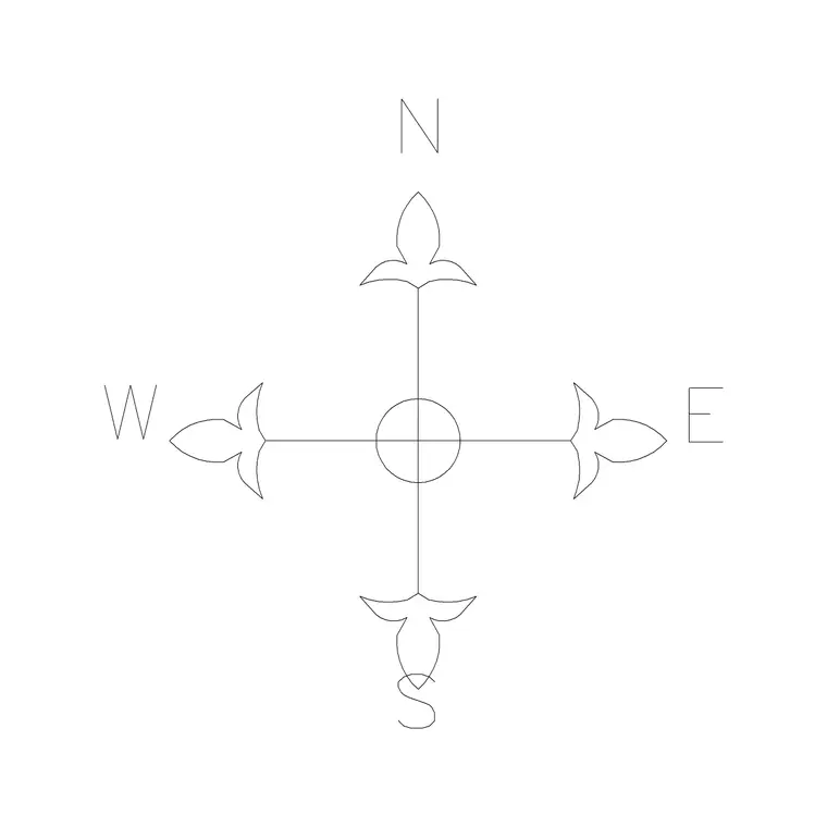
No, one north arrow block like the ones in our building symbols category works across any sheet size, you just need to check the annotation scale so it plots at a legible, consistent size on whichever layout you're using.
Free downloads from this article

Free CAD block library
Download the blocks from this article — free, no signup