Fire Tender Access and Swept-Path Drawings Explained
What fire tender access requires on a site plan, typical guidance figures, and how to rough out an access check using real vehicle and paving blocks.
Saumyajit MaityUpdated 15 June 202611 min read
What fire tender access actually means on a site drawing
Fire tender access is the term used on a lot of UK and Commonwealth site plans for the route a fire engine, sometimes called a pump appliance or fire tender, needs to reach a building closely enough for firefighters to run hoses and ladders effectively, and for the appliance itself to be able to park, turn and leave again without getting stuck. It shows up on a site plan as a dimensioned route, usually a hardstanding strip or dedicated carriageway, running from the public road to a point within a specified distance of the building's fire main connection point or entrance. It's one of those requirements that looks like a footnote on a drawing until building control flags it during review, at which point it becomes the thing holding up your approval.
It's worth treating this as a requirement that gets more demanding, not less, as a building gets taller or larger, since a bigger building generally means a longer hose run to cover, more floor area for firefighters to search and evacuate, and correspondingly stricter access provisions. A small single storey unit and a mid rise apartment block on the same street can end up with meaningfully different fire tender access requirements even though both are, at a glance, just a building next to a road.
Typical figures quoted in guidance documents
The specific numbers are set by whichever building regulation or fire code applies to your project and jurisdiction, so treat anything here as the kind of figure commonly summarized in guidance such as the UK's Approved Document B, not a substitute for checking the actual code your project sits under. A frequently quoted rule of thumb is that a fire appliance access route needs a running width somewhere around 3.7 meters for a single carriageway, with the route needing to bring the appliance within roughly 45 meters of every point of the building it's meant to serve, measured as a hose lay distance rather than a straight line. The surface itself needs to carry the weight of a loaded appliance, often quoted at somewhere in the region of 12.5 to 17 tonnes gross weight depending on the appliance type common to the local fire service.
Guidance in this area is also usually paired with requirements around fire hydrant spacing and, on taller buildings, the position of a dry riser inlet relative to the access route, since the whole point of the route is to get equipment and water close enough to the building fast, and a technically compliant road that lands the appliance a long, uncomfortable hose run from the nearest hydrant defeats the purpose of specifying it in the first place.
Why the exact figures differ between jurisdictions
Part of why it's worth resisting the urge to memorize a single number for fire tender access is that the appliances themselves differ meaningfully between fire services and countries. A fire authority operating older or larger legacy appliances may specify a wider running width or a higher load capacity than one operating a fleet of newer, more compact pump appliances, and a rural fire service sometimes specifies longer hose lay distances than a dense urban one where multiple appliances and hydrants sit closer together. None of this is arbitrary, it reflects the actual equipment a crew will be working with on the day, which is exactly why a generic guidance figure is a reasonable starting point for a first draft layout, not a substitute for confirming the requirement with the fire authority that will actually respond to the building.
Hardstanding, gradient and the load bearing question
The hardstanding itself needs more thought than an ordinary driveway, because it's sized for a much heavier, much less forgiving vehicle than a car. Beyond the running width, guidance typically expects the gradient along the access route to stay gentle, often capped somewhere around 1 in 12 to 1 in 15 depending on the specific document, because a loaded appliance climbing a steep slope in wet conditions is a genuine operational risk, not just a comfort issue. The pavement or hardstanding build up needs a load bearing capacity well beyond a typical car park surface, and this is usually specified as a structural engineering requirement separate from the geometric layout, so a paving CAD block on your drawing represents the finish and joint pattern, not the load bearing base course underneath it, which is a structural detail, not a drafting one.
This is exactly the kind of surface that can look identical to an ordinary car park on a finishes drawing while being a completely different structural build up beneath it, so it's worth cross referencing the fire access zone against the structural engineer's pavement design rather than assuming a consistent hardstanding specification runs across the whole site. A route that's been resurfaced or extended after the original structural design was signed off is a particularly common place for this to quietly go wrong, since nobody necessarily revisits the load bearing calculation just because the visible finish was reapplied.
Hammerhead versus full turning circle
Where an access route ends in a dead end rather than looping back to the road, guidance typically requires a turning facility at the end, either a full turning circle sized for the local fire service's largest common appliance, often quoted in the region of 16 to 17 meters between kerbs, or a hammerhead, T shaped turning area that lets the appliance reverse and pull forward once rather than needing to complete a full circle. Which one your project needs usually comes down to route length: shorter dead end routes are often permitted a hammerhead, while longer ones tend to require the full turning circle, though this really is a local fire authority decision and should be confirmed with them directly rather than assumed from a generic guidance summary.
A hammerhead is typically drawn as a T or plus shaped widening at the end of the access route, sized to let the appliance pull forward into one arm of the T, reverse back out, and then drive forward out of the access route facing the right direction, rather than needing to complete a continuous circular turn. Getting the hammerhead's proportions right on a drawing means checking both arms against the appliance's actual turning geometry, not just eyeballing a T shape that looks roughly right in plan.
Why a fire appliance's swept path differs from a car's
Fire appliances are longer, heavier and have a noticeably different weight distribution than a passenger car, front heavy with the crew cab and pump, and they typically have a wider turning circle and a much longer body overhang at the rear. So a swept path check done against a car's geometry will pass a corner an actual appliance cannot get around. This is exactly why fire service access is usually checked with dedicated appliance dimensions from the relevant fire authority rather than a generic large vehicle assumption, since appliance specifications genuinely vary between fire services and even between appliance types within the same service.
It's also worth remembering that a fire service's fleet isn't a single vehicle type. Aerial appliances with a turntable ladder are typically longer and heavier again than a standard pump appliance, and a route or turning space sized only for the smaller, more common appliance can turn out to be the wrong answer the one time a taller building on the same site needs the aerial appliance to attend instead. Confirming which appliance types the local fire authority expects to use a given route, not just the most frequently seen one, is worth doing before the access geometry is finalized.
Roughing out a check with the blocks we actually have
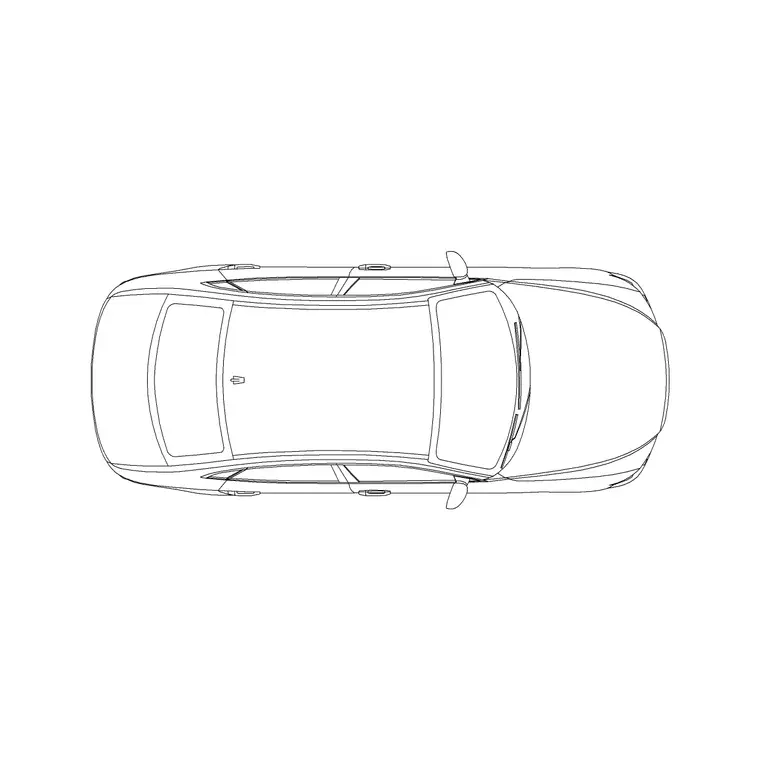
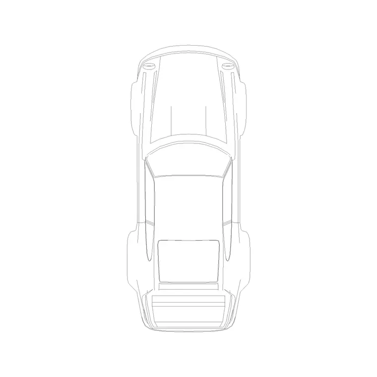
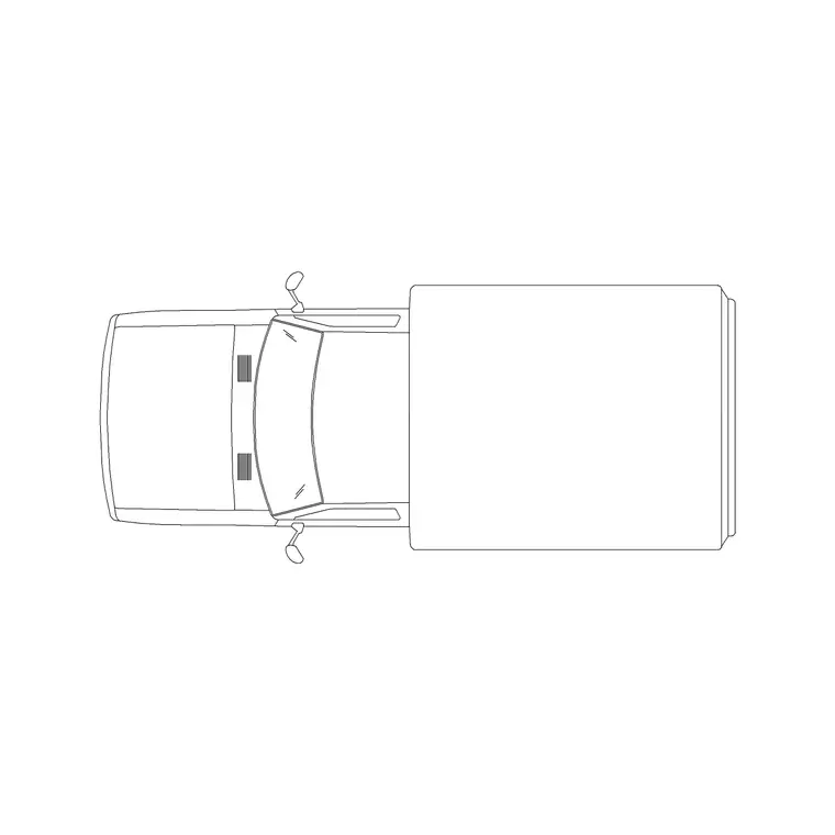
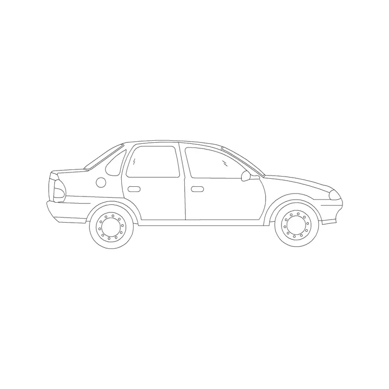
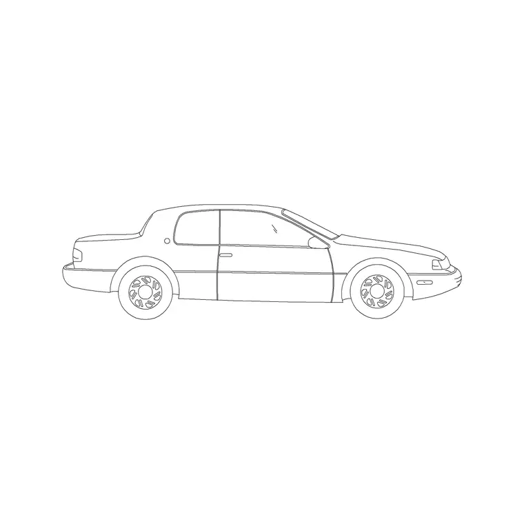
Worth being straightforward here, right: we don't currently carry a dedicated fire engine or fire tender CAD block in the library, so if you're looking for a plug in appliance footprint, that specific download doesn't exist on our site yet. What is genuinely useful at an early design stage is using our large vehicle plan blocks, the suv-car-plan-7 or mini-truck-plan-4 for instance, as a rough stand in to sanity check whether an access route's basic geometry, route width, corner radius, turning space at a dead end, is even in the right ballpark before you commission or run a proper fire appliance swept path analysis.
It's not a substitute for the real check, it's a way to catch an obviously undersized route before you've invested drawing time refining a layout that was never going to work. Once the basic geometry looks plausible, drop in one of our paving blocks, paving-block-1 or paving-block-4, to represent the access route's finished surface for the drawing set, keeping in mind the structural build up underneath is a separate engineering specification entirely.
A worked example: checking a tight junction on a cul-de-sac scheme
Say you're laying out a small residential cul-de-sac scheme where the fire access route has to run in off a fairly narrow existing road and then turn through roughly ninety degrees before reaching a hammerhead at the end. Start the rough check by inserting the suv-car-plan-7 block, or the mini-truck-plan-4 if you want a slightly larger stand in, at the point where the access route meets the existing road, oriented along the road's own centerline, then copy and rotate it through the turn at three or four stations the way you would for an ordinary swept path check. What you're really looking for at this early stage isn't a precise pass or fail, since these blocks are stand ins rather than the actual appliance geometry, it's whether the turn is obviously going to be a problem, a corner so tight that even a large SUV's rough footprint can't get around it without multiple shunts, in which case there's no point spending design time refining the hammerhead proportions until the junction itself is widened. If the rough check clears comfortably, that's your cue to commission the proper fire engineer's swept path analysis with the actual appliance dimensions, confident you're not about to be told the whole junction geometry needs revisiting from scratch.
Marking the route clearly on the drawing set
Beyond getting the geometry right, a fire tender access route is worth marking distinctly on your site plan rather than leaving it to blend into the general circulation layout, since building control reviewers and, more importantly, an attending fire crew unfamiliar with the site benefit from being able to identify the route at a glance. A common convention is to hatch or tint the access route differently from ordinary parking and driveway surfaces, label it explicitly as fire access with the required width called out, and cross reference it to a dedicated fire strategy drawing where one exists rather than relying purely on a note buried in a specification. It's also worth explicitly marking the route as a no parking, no obstruction zone on the same drawing, since an access route is only as good as the enforcement that keeps it clear of parked cars and wheelie bins on the day it's actually needed.
Coordinating fire access with landscaping and street furniture
One thing that catches out a lot of otherwise solid fire access designs is coordination with everything else that gets added to a site plan after the access route itself is signed off, street trees, cycle stands, refuse store enclosures, even temporary skips during construction. A route that was correctly dimensioned and gradient checked at the design stage can quietly stop working the moment a landscape architect adds a row of semi-mature trees along its edge without checking canopy spread against the appliance's actual swept width, or a waste contractor's bin store ends up sited a meter into what was meant to be clear hardstanding. This is really a drawing coordination problem more than a design one, and the fix is straightforward if you build the habit early: keep the fire access route and its associated clearance zone on its own dedicated layer that gets checked against every other discipline's drawing before anything is finalized, rather than trusting that everyone downstream remembers a note buried in a specification document. It's also worth adding the access route explicitly to any landscape or street furniture drawing as a simple hatched overlay, since a landscape architect working from a base plan that doesn't show the fire route at all has no real way to know it's there to avoid.
When to bring in a professional
Anything genuinely feeding into a building control submission or a fire strategy report should go through a swept path analysis done with the actual fire service's appliance dimensions, usually by a fire engineer or access consultant using dedicated vehicle tracking software, and ideally confirmed directly with the local fire authority since access requirements and appliance specifications aren't identical everywhere. Treat everything in this article, and any manual block based check on your own drawing, as the design development stage sanity check it is, not the final compliance evidence.
In practice this is rarely a single discipline's decision either: the fire engineer confirms route length and turning requirements, the structural or civil engineer confirms the hardstanding's load bearing build up, and the landscape architect needs to keep tree canopies and low branches clear of the route's vertical envelope, since an appliance needing height clearance for its ladder or aerial equipment can be blocked by planting that looked perfectly reasonable on a landscape drawing done in isolation.
Further reading
Questions
Frequently asked
What is fire tender access?+
It's the dimensioned route and hardstanding a fire appliance needs to reach a building closely enough to fight a fire effectively, covering route width, gradient, load capacity and turning space, all set by the fire code or building regulation applicable to your project.
How wide does a fire access route need to be?+
UK guidance commonly summarizes a single carriageway fire access route at around 3.7 meters running width, though the exact figure depends on the specific code and local fire authority requirement for your project.
Do you sell a fire engine CAD block?+
Not currently. Our large vehicle plan blocks can be used as a rough early stage stand in to sanity check route geometry, but a genuine fire appliance swept path check should use the actual appliance dimensions from the local fire authority.
Is a car's turning circle a reasonable substitute for a fire appliance's?+
No. Fire appliances are longer, heavier and have different overhang and turning characteristics than a car, so a route that clears a car's swept path can still be too tight for an actual fire engine.
Free downloads from this article



Free CAD block library
Download the blocks from this article — free, no signup