Electric socket and switch CAD blocks for an office power plan
Using socket and switch DWG blocks to complete an office power plan, with realistic mounting heights and desk circuit spacing.
Saumyajit MaityUpdated 12 May 20266 min read
Furniture layout isn't finished until the power plan is
I've handed over furniture layouts that looked complete, every desk placed, every conference table centred, and then gotten the call two days later asking where the sockets go, because a workstation layout without a power plan behind it is basically a nice picture, not a buildable drawing. Electric socket and switch CAD blocks are the unglamorous part of an office layout that nobody notices when it's done right and everybody notices when it's missing, so I've made it a habit to drop the socket layer in right after the furniture layer, not as an afterthought at the end of the project.
What the socket and switch block actually gives you
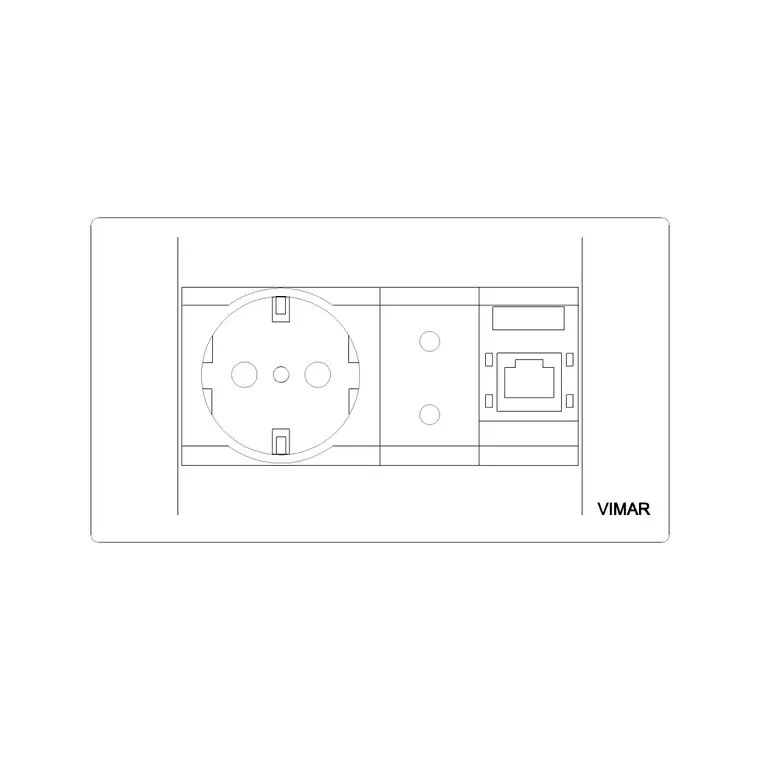
The electric socket vimar 1 block on the site is drawn as a plan symbol, the kind you'd place along a skirting run, behind a desk leg, or on a reception counter face, and it inserts as a compact single object so you're not redrawing the little rectangle and prong symbol every time you need one on the plan. These are typically drawn at a scale that reads clearly at 1:50 or 1:100 without cluttering the drawing, and because it's a symbol block rather than a full 3D fixture, it inserts fast and stays lightweight even when a floor plan has dozens of them scattered across workstations, the reception desk, and the break room.
Realistic mounting heights to plan around
For a general office fit out, floor or skirting level sockets typically sit around 150 to 300 mm above finished floor level, which works for desk lamps, floor standing printers, and general power. Desk mounted or under desk sockets, common on modern workstation with partition setups where cable management runs through the desk frame, usually sit closer to worktop height, roughly 700 to 750 mm, so cables don't trail across the floor at all. Switches for lighting are a different height range entirely, typically around 1200 to 1350 mm above finished floor, comfortable reach height for most adults, and I keep switch blocks on a separate layer from power sockets so an electrical contractor can isolate lighting circuits from power circuits at a glance.
Planning sockets around workstation clusters
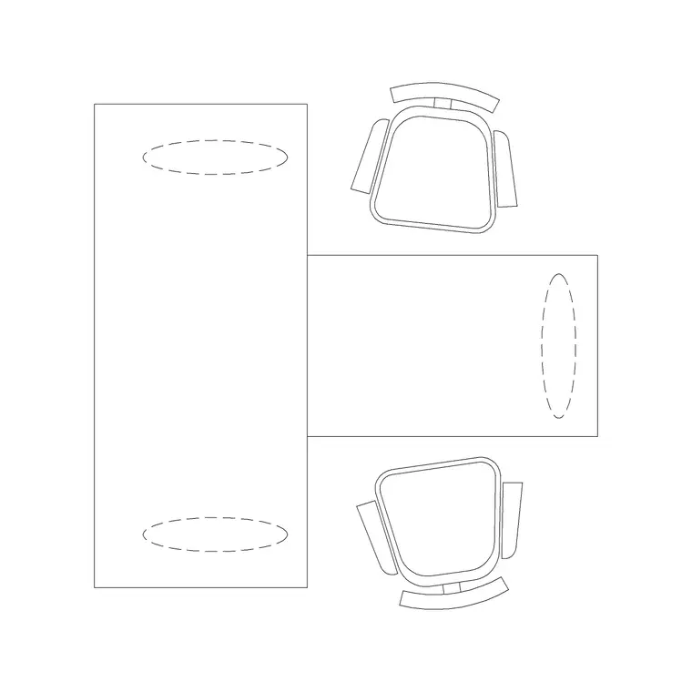
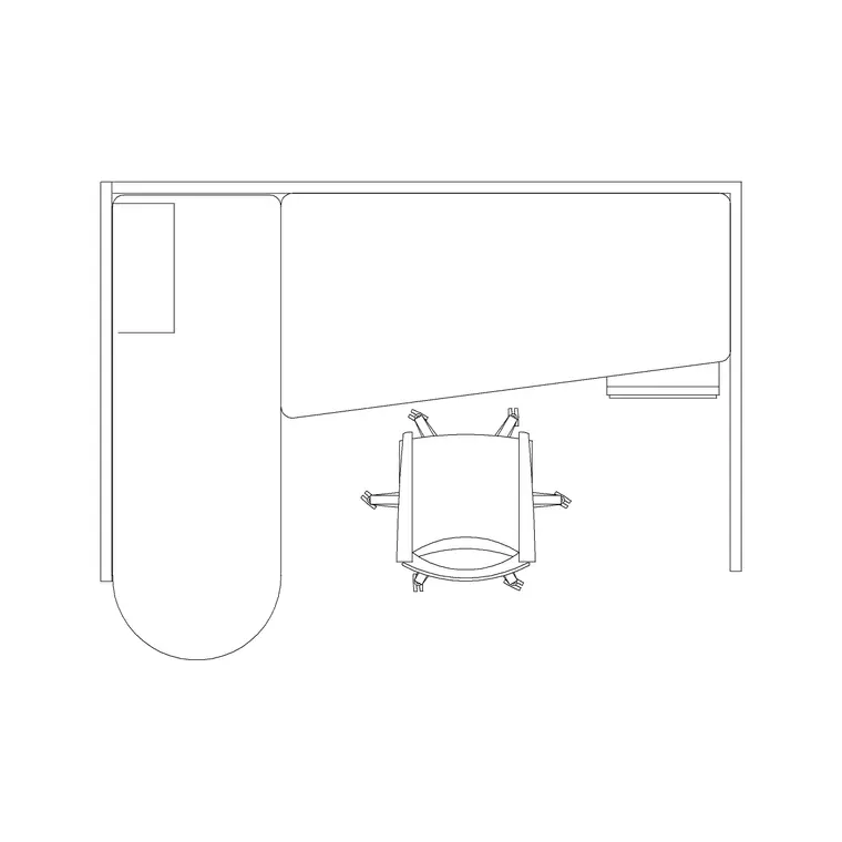
For a bullpen built from 2-seater workstation blocks, I typically plan for at least one dual socket per desk position, sometimes doubled up if the client's IT team wants a dedicated circuit for monitors versus a general use outlet for phone chargers and desk fans. Where clusters get power from an overhead busbar or a floor box instead of wall sockets, the socket block still matters on the plan, it just moves location, from the perimeter wall down into a floor box symbol positioned at the centre of the cluster, usually right where the cable trough of the desk block sits.
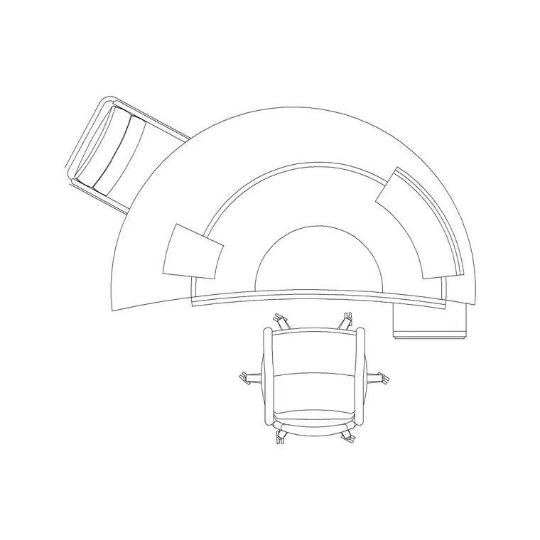
For a reception desk or a manager's office, plan for at least two to three sockets near the working surface, one for the computer, one spare for a phone charger or desk light, and don't forget a switch near the door for the room's main lighting circuit.
Bringing socket blocks into the drawing cleanly
Insert the socket block onto a dedicated electrical layer, separate from furniture and from architectural walls, so you can toggle it off when you're presenting a pure furniture layout to the client and toggle it back on for the services drawing. Use a consistent insertion point, usually the centre of the symbol, and snap to the wall face rather than eyeballing the position, since electrical contractors will pull dimensions straight off your drawing to set boxes on site. If you're placing dozens of sockets across an open plan floor, copy the block along a path rather than inserting one at a time, it keeps spacing consistent and saves a genuinely tedious amount of clicking.
It's also worth checking scale one more time before you finalise the electrical layer, since a symbol block that looks correctly sized at 1:50 can read as an oversized blob at 1:100 or disappear into an unreadable dot at 1:200, and a power plan nobody can actually read at the printed scale defeats the point of drawing it carefully in the first place. I generally do a print preview at the actual sheet scale before sending anything out, just to confirm the socket and switch symbols are still legible next to the dimension strings and room labels.
The pitfall that catches almost everyone once
The mistake I see most, and made myself early on, is placing sockets purely based on where the furniture sits in the current layout, then having the whole plan reshuffle two weeks later when the client changes the workstation count, leaving half the sockets stranded behind a wall with no desk near them. What I actually do now is plan power roughly on a grid, spaced to serve any reasonable furniture layout rather than one specific arrangement, because furniture moves far more often during a project than the electrical rough in does, and a power plan tied too tightly to one layout ages badly the moment anything shifts.
The other thing worth double checking before you send the drawing out is circuit grouping, not every socket on the plan needs to be on the same circuit, and a good power plan usually notes which sockets are general power versus which are on a dedicated or UPS backed circuit for server racks, network switches, or anything the client can't afford to lose during a power blip. That detail doesn't have to live in the block itself, but a simple tag or a note layer next to each socket group saves the electrical contractor a round of questions later, and it's the kind of thing that separates a furniture plan with symbols scattered on it from an actual usable power layout.
Data and network outlets ride along the same layer
Power sockets rarely travel alone in a modern office, most workstation positions also need a data outlet nearby for a wired network connection, even in offices that lean heavily on WiFi, since a hardwired connection is still the more reliable choice for a desktop workstation or anything running a video call on a shared network. I keep a separate but visually similar symbol for data outlets on the same electrical layer as power sockets, distinguished by a different hatch or a small label rather than a completely different block style, so the layer stays legible without needing two separate legends on the sheet.
The practical reason to plan these together rather than as an afterthought is that a data outlet and a power socket serving the same desk position usually want to land at the same general location, often in the same floor box or the same section of skirting trunking, so a low voltage contractor and an electrical contractor aren't running separate conduit runs to nearly the same spot on site. Coordinating that placement on the drawing, even just by grouping the symbols visually next to each other at every desk position, saves a round of on-site conflict resolution between two trades who'd otherwise be working from the same furniture plan without talking to each other.
Further reading
Questions
Frequently asked
What height should office wall sockets be drawn at on the plan?+
General skirting level sockets typically sit around 150 to 300 mm above finished floor level, while desk mounted sockets on modern workstations usually sit closer to worktop height, around 700 to 750 mm.
Should socket and switch blocks go on the same layer as furniture?+
No, keep electrical symbols on their own dedicated layer so you can toggle the power plan on or off independently of the furniture layout, which makes it much easier to hand a clean drawing to a contractor.
How many sockets should I plan per workstation in an office layout?+
A common baseline is at least one dual socket per desk position, sometimes doubled for a separate monitor and general use circuit, though this depends on whether the client wants dedicated IT power.
Free downloads from this article
Free CAD block library
Download the blocks from this article — free, no signup