Converting DWG to PDF Without Losing Lineweights
Why plotted PDFs sometimes lose their lineweight hierarchy, and the plot style and driver settings that keep heavy and light lines distinct.
Saumyajit MaityUpdated 18 April 202611 min read
The complaint I hear most about DWG to PDF
I plot a drawing to PDF and every line comes out looking the same weight, the heavy wall outline, the light hatch boundary, the fine dimension extension line, all flattened to one uniform thickness on screen. It is one of the most common frustrations in a plotting workflow, and it almost never means AutoCAD has a bug, it means something in the plot configuration between the drawing and the PDF driver is discarding lineweight information along the way.
Once you know where lineweight actually lives and how it travels through the plot process, the fix is usually a couple of settings rather than a mystery.
What makes this particular problem sneaky is that it often goes unnoticed until the exact moment it matters most, a submission set going out to a client or an authority, since the drawing has looked correct on screen the entire time and the flattening only shows up in the exported file itself. Building the habit of checking a plotted PDF specifically, not just the drafting view, before anything leaves the office removes that nasty last minute discovery entirely.
Where lineweight actually comes from
A lineweight can be assigned two ways, directly to an object or a layer as a fixed property, or indirectly through a plot style that maps a colour or a named style to a specific weight at plot time. Whether you see that weight on screen while drafting depends on the LWDISPLAY system variable, which toggles a purely visual preview in Model space and has zero effect on what actually plots, which is worth knowing because people sometimes panic that their lineweights are wrong when LWDISPLAY is simply switched off.
What actually plots is controlled by the plot style assigned at print time, not by whatever you happen to see on your monitor while drafting, and that distinction is the root of most lineweight confusion.
A quick way to see this in action, toggle LWDISPLAY on and check the status bar Lineweight button in Model space, lines that were always plotting with correct weight will suddenly show visibly different thicknesses on screen, nothing about the drawing changed, only whether you happen to be previewing what was already true the whole time. Getting comfortable with that distinction early saves a lot of confused troubleshooting later, since screen appearance and plotted output are simply answering two different questions.
Colour dependent versus named plot styles
AutoCAD gives you two plot style systems. Colour dependent plot style tables, the CTB files, assign a lineweight and other print properties based purely on an object's colour, so everything drawn in a particular colour plots at a particular weight regardless of layer. Named plot style tables, the STB files, instead assign properties directly to a style that you attach to objects or layers independent of colour.
Neither is universally correct, CTB is the older, still very common approach in a lot of AutoCAD based offices, STB tends to suit workflows where colour is doing something else entirely, like representing material or category rather than print weight. What matters for lineweight fidelity is that whichever system your office uses, the table you select at plot time actually has the weights assigned the way you expect, since a generic or default table that maps everything to one weight is a very common silent cause of flat looking output.
Switching between the two systems mid project is where real trouble starts, a drawing built up assuming colour dependent weight assignment can plot with an entirely different hierarchy if someone later applies a named style table without checking, since the two systems are not simply interchangeable views of the same information, they are two separate ways of deciding weight in the first place. Confirm which system a drawing was built around before touching its plot style table dropdown, especially on a file inherited from another office or consultant.
The DWG to PDF driver and one checkbox that matters
The DWG to PDF.pc3 driver that ships with AutoCAD produces vector PDF output by default, which is exactly what you want for crisp, scalable lineweights, but only if the plot dialog is actually told to apply your plot style table. The Plot dialog has a Plot Style Table dropdown, and a Plot with Plot Styles checkbox nearby that has to be ticked for that table's weight assignments to actually apply to the output.
Miss that checkbox, or leave the plot style table set to none, and AutoCAD will happily produce a PDF where every line plots at its raw, unmodified object lineweight instead of the styled hierarchy your table was meant to enforce, which is the single most common reason a plotted PDF looks visually flatter than the drawing does inside AutoCAD.
This setting is saved per page setup, not globally, which is exactly why it catches people, a new layout tab created by copying an old one sometimes carries the setting forward correctly, and sometimes does not, depending on exactly how it was created. Rather than assuming a new layout inherited the right configuration, open its Plot dialog once and confirm the checkbox and table explicitly before relying on it for anything that will leave your desk.
This is exactly the kind of setting that survives quietly for months without anyone noticing, since most day to day plotting checks the geometry and the sheet layout, not the plot style dropdown specifically, so it is worth a periodic audit across a project's layouts rather than a one time check at project kickoff alone.
Other quiet ways lineweights get lost
Beyond the plot style checkbox, a few other habits quietly flatten output. Plotting Model space directly with LWDISPLAY off can make you assume weights are wrong when they are simply not previewed, so always trust the plot preview, not the drafting view. Using a monochrome style table converts colour to black for print, which is fine and common, but should still respect whatever lineweight was assigned, if it does not, check that Use Object Lineweight has not been switched off within that specific table's settings.
Downstream PDF processing is another quiet culprit, running a plotted PDF through aggressive compression or flattening in a separate PDF editor afterward can merge or thin fine hairlines that were perfectly intact straight out of AutoCAD, so if your workflow includes a post processing step, check the output at both ends of it.
One more habit worth building, if your office keeps a standard title block or border with fine hairline rules around a schedule table, treat that as a canary for the whole sheet, since it is usually the thinnest, most consistent linework on the page. If a title block border prints crisp and consistent, the rest of the sheet's lineweight hierarchy is very likely intact as well, and if it looks flattened or inconsistent, that is a fast, reliable signal to go back and check the plot style configuration before the sheet goes any further.
A quick example: the one sheet in a set that didn't match
A concrete example of exactly this going wrong, since it is more useful than the abstract version, a full sheet set went out for a client review recently and every sheet looked correct except one, a detail sheet that had been copied into the set from an older project file rather than built fresh alongside the rest. Every other layout in the set inherited the current page setup correctly, plot style table selected, Plot with Plot Styles ticked, but that one copied layout had quietly carried its old page setup along with it, pointing at a different, generic plot style table that flattened everything to a uniform weight. Nothing about the sheet looked wrong inside AutoCAD itself, since LWDISPLAY was switched on and the drafting view showed proper weight variation, the problem only became visible in the plotted PDF, which is exactly the kind of thing that slips through a review if nobody opens the actual exported file sheet by sheet before sending it out.
The fix was straightforward once spotted, open that one layout's Page Setup, point it at the same named page setup the rest of the set already used, and replot just that sheet, but the real fix going forward was a process change rather than a one-off correction, checking every layout's page setup explicitly whenever a sheet gets copied in from an older file, rather than trusting that copying a layout also copies a correctly configured plot style along with it. It usually does, which is exactly why the one time it does not is so easy to miss, since the habit of assuming it is fine is reinforced by it actually being fine the overwhelming majority of the time.
That is really the underlying lesson worth carrying forward, a consistent plotted result across a whole sheet set is not something you can spot check on one or two sheets and assume holds for the rest, it is worth genuinely opening the exported PDF and flipping through every sheet before a set goes out the door, especially on a project where sheets have been assembled from more than one source file over time, since that is exactly the situation where one layout quietly diverging from the rest is most likely to happen.
A reliable step by step workflow
- Confirm every layer or object that should carry a specific lineweight actually has it assigned, rather than relying on a default. - Pick CTB or STB to match your office's existing standard, do not switch mid project. - In the Plot dialog, select the correct plot style table and make sure Plot with Plot Styles is checked. - Use Page Setup Manager to save this configuration as a named page setup so every sheet in a set plots identically without re-picking settings each time. - Check the plot preview specifically, not the drafting view, before committing to a full print run. - For a multi sheet set, use PUBLISH to apply saved page setups consistently rather than plotting sheets one at a time by hand.
Following that sequence removes almost all of the accidental flattening that shows up in DWG to PDF conversions done in a hurry.
Vector output versus a rasterised PDF
A vector PDF, which is what DWG to PDF.pc3 produces by default, preserves stroke widths as actual scalable vector strokes, so a heavy wall line stays visibly heavier than a hairline dimension no matter how far you zoom into the PDF later. A rasterised PDF instead bakes everything into pixels at a fixed resolution, and at a low enough DPI, fine hairline distinctions genuinely start to blur or disappear entirely, which is a different failure mode from the plot style issue above but produces a visually similar complaint.
If you ever find yourself deliberately rasterising output, for instance to shrink file size for email, keep the resolution high enough that fine linework survives, since that tradeoff is invisible until someone zooms in on a detail sheet and finds a hairline has vanished.
A reasonable middle ground when file size genuinely matters, keep the vector PDF as the authoritative deliverable and produce a separate, smaller raster version specifically for email or quick reference, rather than compressing the one file everyone actually relies on for measurements and construction detail. That way the file people zoom into for real work never loses fidelity, only the throwaway copy does.
Why this matters even more on detail heavy sheets
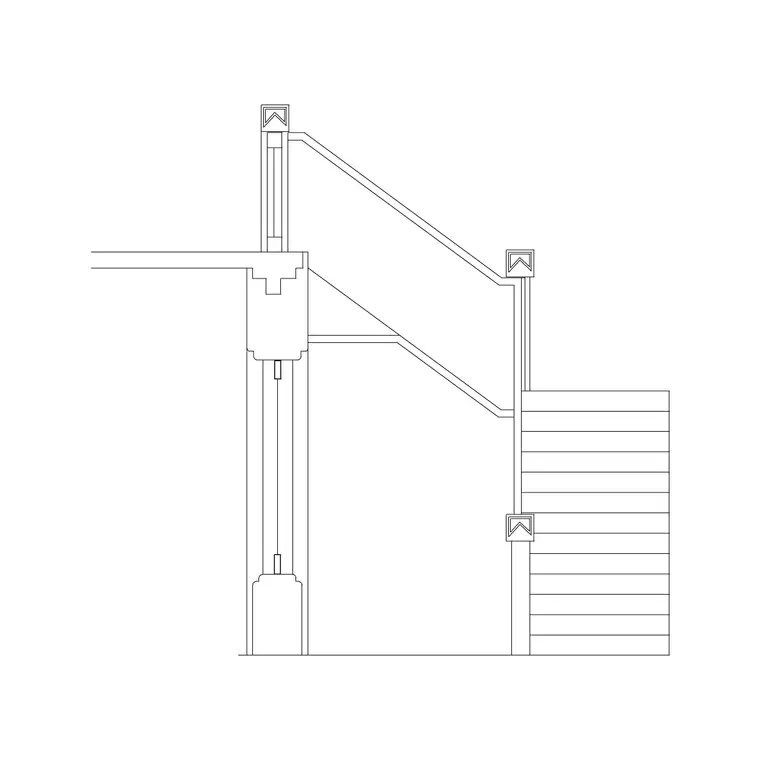
Sheets carrying a lot of fine linework, a door schedule with hairline leader lines, a stair detail with closely spaced tread lines, a window elevation with thin glazing bars, are exactly where a flattened lineweight hierarchy is most obvious and most damaging to legibility. A reviewer glancing at a stair elevation like Metal Staircase Front Elevation 1 needs the tread lines to read distinctly from the outline weight at a glance, and that only survives the PDF conversion if the plot style pipeline described above is set up correctly before you hit print.
Treat lineweight verification as a standard step before any external submission, not an afterthought you only check when someone complains, and this entire category of avoidable rework disappears from your process.
A simple final check that catches most remaining issues, open the exported PDF at actual plotted size, not zoomed to fit the screen, and compare a heavy line against a light one side by side. If the distinction is obvious at true size, the pipeline is working, if it is not, walk back through the plot style table, the checkbox, and the driver resolution in that order, since those three settings account for nearly every case of lineweight loss covered here.
Once a page setup produces a genuinely correct result, save it, name it clearly, and reuse it rather than rebuilding the same set of choices from memory on the next drawing. A verified, named page setup is the single artefact that actually carries this whole workflow forward reliably from one project to the next, everything else covered here is really just the reasoning behind why that particular configuration works.
If your office produces enough drawings that this configuration needs to travel between projects and even between machines, save the verified page setup into your standard template file rather than recreating it drawing by drawing, so every new project starts from a page setup already known to plot correctly, and lineweight fidelity becomes the default outcome rather than something checked and fixed after the fact each time.
Further reading
Questions
Frequently asked
Why do my lineweights look fine on screen but flat in the exported PDF?+
Almost always a plot style table issue, either the wrong table selected at plot time or the Plot with Plot Styles checkbox left unticked, so the raw object weights print instead of your styled hierarchy.
Should I use a CTB or an STB plot style table?+
Neither is universally correct. CTB assigns weight by colour and is common in older AutoCAD based offices, STB assigns weight directly to objects or layers independent of colour. Match whatever your office already standardises on.
Does the DWG to PDF driver produce vector or raster output?+
Vector, by default, which preserves lineweights as scalable strokes. It only becomes raster if you deliberately lower the output resolution or flatten the file afterward.
Can editing a PDF afterward damage its lineweights?+
Yes. Aggressive compression or flattening in a separate PDF tool after export can merge or thin fine hairlines that were intact straight out of AutoCAD, so check output quality at both ends of any post processing step.
Free downloads from this article


Free CAD block library
Download the blocks from this article — free, no signup