Choosing vehicle blocks for an accurate turning-radius study
A turning-radius study needs the right view type, not just the right vehicle. Here's how to pick vehicle CAD blocks that actually hold up.
Sumana KumarUpdated 4 April 20265 min read
The single mistake that undoes a turning study
I've reviewed enough turning-radius studies to know the most common way they go wrong isn't a bad radius calculation, it's the vehicle block itself. Someone inserts a car elevation, a perfectly good side-profile silhouette, directly into a plan-view drawing and starts sweeping an arc around it, and the whole exercise is compromised from that point on because an elevation was never meant to represent a footprint.
The frustrating part is that this mistake is genuinely easy to miss on a quick review, since the resulting drawing still looks plausible at a glance, an arc, a vehicle shape, a dimension callout, all present and looking the part. It's only when someone checks the actual wheelbase and overall width the arc was drawn against that the error surfaces, and by then it's often after the drawing has already been circulated or submitted, which is a genuinely avoidable waste of time for everyone involved.
Elevation blocks are not footprints
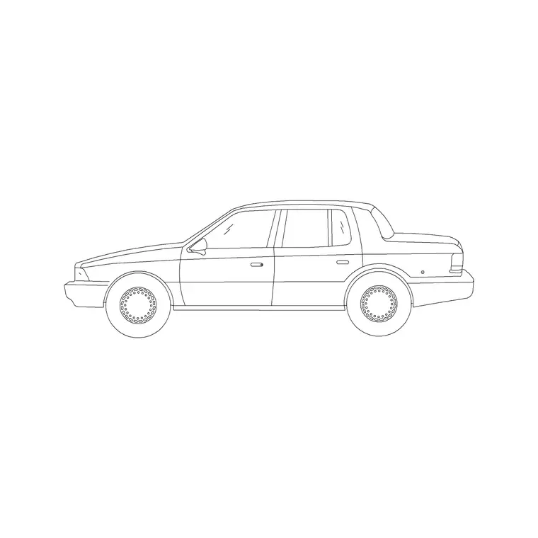
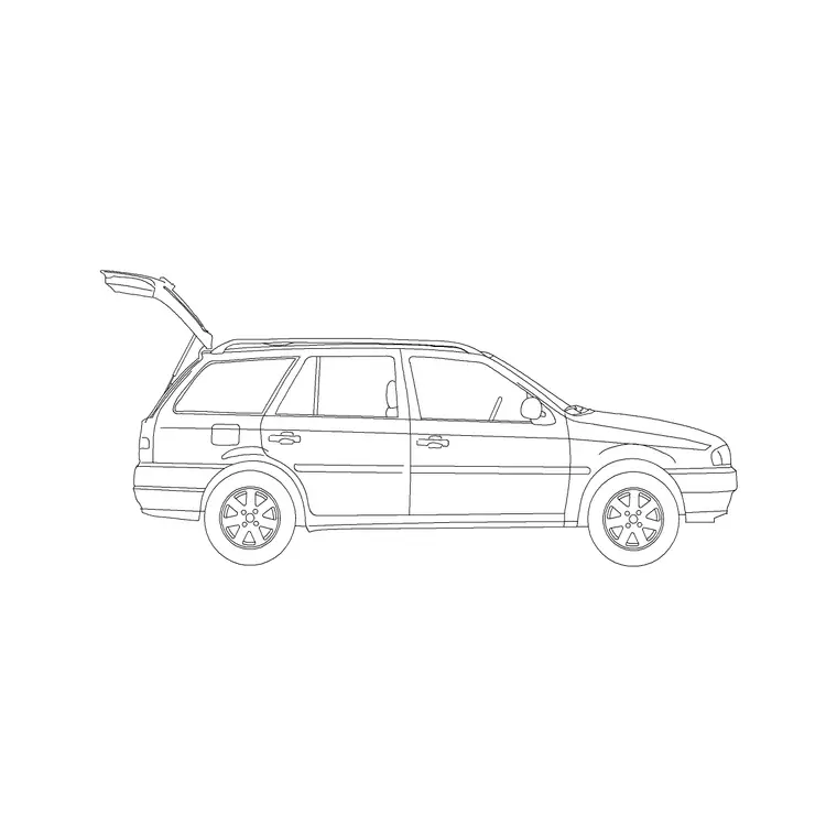
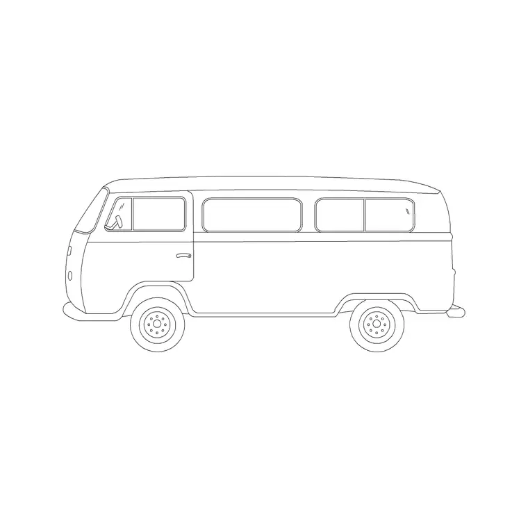
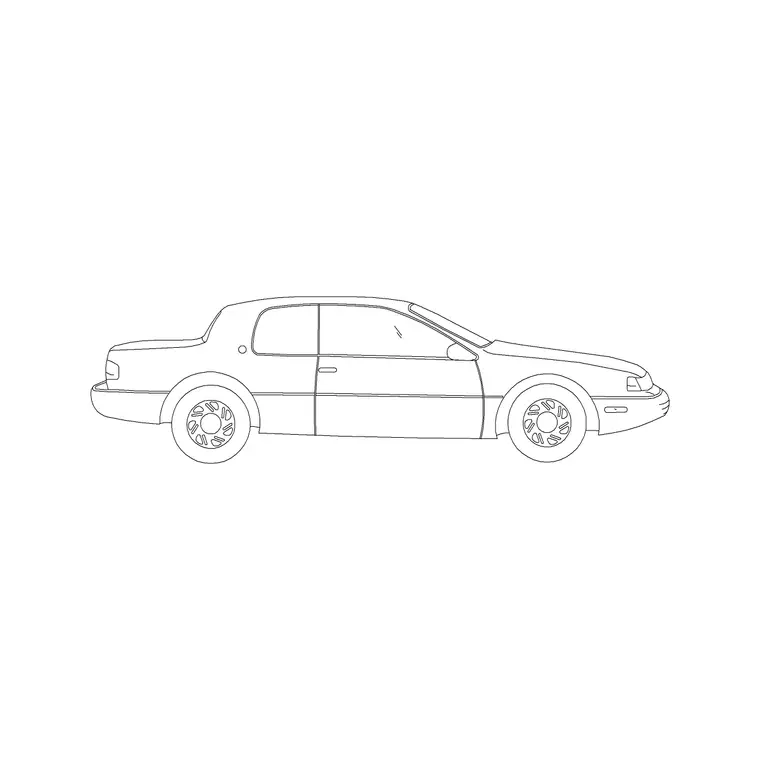
Most of the named vehicle blocks on cadblockdwg.com, the Sedan Car, SUV Car, 2 Door Sedan Car, Sports Car and Convertible Car among them, are elevation views, side-profile silhouettes built for building elevations and streetscapes. They're genuinely useful for showing that a car is present and roughly how it reads visually, but they carry no reliable plan-view footprint information, and using one to trace a turning circle will give you a shape that looks plausible but isn't actually derived from the vehicle's real overall width or wheelbase.
What you actually need instead
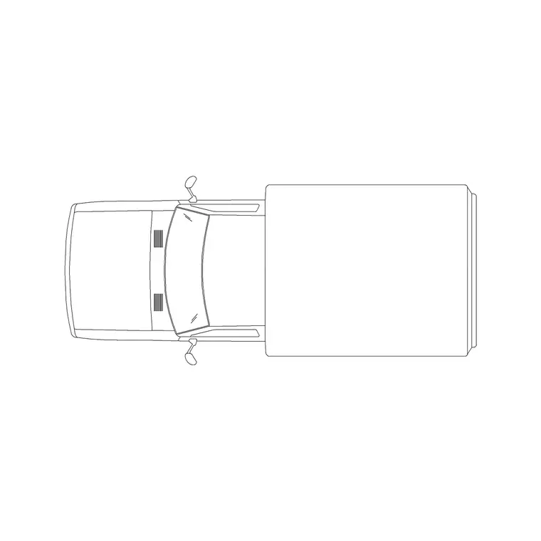
For a real turning-radius study you need a genuine plan, or top-view, block, and that's exactly what the Mini Truck Plan block on the site gives you, a true top-down footprint you can use as the base for tracing an approximate swept path or minimum turning circle. If your library has additional plan-view car blocks alongside it, and the vehicles category does carry several, that's the family of blocks to reach for whenever the drawing is checking manoeuvrability rather than showing a parked or passing vehicle.
What I actually check first when I open any 'vehicle' block for this purpose is the preview thumbnail, not the file name, since names alone don't always tell you which angle a block was drawn from. A genuine plan view shows the roof outline and wheel positions from directly above, no windshield, no grille, no wheel arches in profile, and if what you're looking at instead shows a recognisable side silhouette, it's an elevation and it's the wrong block for a turning study no matter how convincing the file name sounds.
Using the elevation blocks as supporting context, not the study itself
That doesn't mean the elevation blocks are useless on a turning-radius sheet, I'll often keep a Sedan Car or Van elevation tucked into a corner of the same drawing purely as a visual key, so a reviewer glancing at the sheet immediately understands which vehicle class the study is for, without mistaking that reference image for the actual geometry being swept. Just be explicit in your notes or a callout that the elevation is illustrative and the plan-view block is what the turning path is actually based on, so nobody downstream confuses the two.
Practical steps for a clean study
Start by inserting the plan-view vehicle block at a verified scale, checking it against a known dimension such as the roughly 4.5 to 6.0 metre length typical of the vehicle class you're studying, before you draw a single arc. Trace the turning path from the block's actual wheel positions where you can identify them, rather than from the outer body outline, since the true minimum turning circle is governed by the front wheels, not the bodywork.
Both the Mini Truck Plan block and the elevation blocks download as DWG and insert the same way with the INSERT command, the only real difference is which angle they were drawn from, so this is entirely about picking the right view for the job rather than anything to do with file format or import method.
Treat a rough study block as exactly that, rough
It's worth being upfront about the limits of a generic downloaded vehicle block in this context. A turning-radius study built from a Mini Truck Plan block gives you a genuinely useful approximate footprint for early-stage layout checks, working out roughly whether a proposed access road, a loading court or a car park aisle has any chance of accommodating the vehicle in question, but it is not a substitute for a proper swept-path analysis using dedicated vehicle-tracking software once a scheme is far enough along to need one.
What I actually use these blocks for is the first-pass sanity check, the stage where you're testing whether a layout concept is even plausible before investing time in a full tracking study. If the rough footprint clearly won't fit a proposed manoeuvre, you know immediately the layout needs rethinking. If it looks like it might just work, that's exactly the point to hand it off to proper swept-path software, or a transport consultant if the project has one, rather than relying on a hand-traced arc around a generic block for anything that will end up in a formal submission.
Basically, generic CAD blocks are brilliant for speed and for catching obvious problems early, they're not a substitute for vehicle-specific tracking data once accuracy actually matters to a planning authority or a highways reviewer, and being clear about which stage of the project you're in saves you from either over-engineering an early concept sketch or under-engineering a final submission.
Noting the assumed vehicle envelope directly on the sheet
One habit that saves a lot of downstream confusion is labelling the actual vehicle dimensions the turning path was built against, directly on the drawing rather than leaving it implicit in the block you happened to insert. A simple callout next to the swept path, something like 'turning path based on generic light commercial vehicle, wheelbase approximately X, overall width approximately Y', means anyone reviewing the drawing months later, a colleague picking the file back up, a client's transport consultant, a planning officer, can immediately see what assumption the arc was drawn against rather than having to reverse-engineer it from the geometry.
I picked up this habit after being asked more than once in a design review to justify exactly which vehicle a turning circle was based on, and not having an answer beyond 'the block I downloaded' is a genuinely awkward position to be in. It takes thirty seconds to add the note at the time you draw the arc, and it saves a considerably longer conversation later trying to reconstruct your own reasoning from a drawing with no record of it.
Further reading
Questions
Frequently asked
Can I use a car elevation block for a turning-radius study?+
Not for the geometry itself. Elevation blocks are side-profile silhouettes with no reliable plan-view footprint, so use them only as a visual reference key, and base the actual swept path on a genuine plan-view block.
Which block on the site is a true plan view for this purpose?+
The Mini Truck Plan block is a genuine top-view footprint, making it the right base for tracing an approximate turning circle or swept path.
Where should the turning path actually be traced from on the vehicle?+
From the wheel positions where identifiable, not the outer body outline, since the minimum turning circle is governed by the front wheels rather than the bodywork silhouette.
Free downloads from this article
Free CAD block library
Download the blocks from this article — free, no signup