Boom Barrier, Bollard and Gate Spacing for Site Entrances
Practical spacing and clearance guidance for boom barriers, bollards and vehicle gates at site entrances, checked against real vehicle CAD blocks.
Sumana KumarUpdated 20 July 202611 min read
Three different jobs: barrier, bollard, gate
A site entrance often ends up with three different control devices doing three genuinely different jobs, and it's worth being clear about which is which before laying out spacing, because designing them as if they were interchangeable is where a lot of entrance drawings go wrong. A boom barrier controls access by raising and lowering an arm, its whole purpose is to let an authorized vehicle through while stopping an unauthorized one, and it needs to be paired with something that stops a driver simply steering around the end of the arm. Bollards are fixed, or sometimes removable, posts that physically block a vehicle from a specific zone, a footpath, a building frontage, while still letting a pedestrian or wheelchair user pass between them. A gate is a full width barrier, solid or open, that closes a vehicle route entirely when shut, typically used where a site needs to be fully secured outside operating hours rather than just access controlled during them.
A lot of real entrances actually combine two or even all three of these, a boom barrier for routine daytime access control paired with a full gate that closes behind it overnight, plus a run of bollards protecting the adjacent pedestrian frontage from a vehicle simply mounting the kerb beside the controlled opening. Planning for that combination from the start, rather than adding devices one at a time as issues come up, is what keeps the overall entrance geometry coherent rather than a patchwork of retrofits.
Boom barrier arm length, clearance and operation type
Boom barrier arms are supplied in a range of standard lengths, and choosing one usually comes down to matching the arm to the lane width you actually need to cover, commonly available in arm lengths from around 3 meters up to 6 meters for a standard single lane, with longer arms available for wider spans though they typically need additional support, a folding arm or a mid span support post, once the length gets much beyond that, since an unsupported arm that long sags and becomes unreliable. The barrier housing itself needs clearance to the side for the arm to swing up fully, and this clearance zone is easy to forget when a barrier gets positioned close to a wall or a kerb line without checking the arm's fully raised position.
Boom barriers are also broadly available as manual, spring assisted manual, or fully automatic electric operated units, and the choice affects more than convenience, it affects how quickly the barrier can respond to traffic and what backup arrangements are needed if power fails. A fully automatic barrier at a busy entrance is usually paired with a manual override or a battery backup so the arm can still be raised during a power cut, since a barrier stuck in the down position at a busy site entrance during an outage creates exactly the kind of queuing and access problem covered later in this article. Rising arm barriers, the common boom design, are more compact at the housing but need the vertical swing clearance covered above; folding arm barriers fold in the middle rather than swinging a single long arm upward, which is a useful option where overhead clearance is limited, at some cost in mechanical complexity.
Bollard spacing for vehicle restriction versus pedestrian access
Bollard spacing is a genuinely fine balance: spaced too far apart and a small vehicle or motorcycle can squeeze between them, spaced too close and a wheelchair user or a pushchair can't get through. General accessibility guidance in a lot of markets suggests a clear gap somewhere in the range of 1 to 1.5 meters between bollards where pedestrian access needs to be preserved alongside vehicle restriction, wide enough for a wheelchair or mobility scooter but tight enough that a car genuinely can't pass through. Where the goal is purely vehicle restriction with no pedestrian route intended between the bollards, spacing can be tighter, though local guidance and site specific risk assessment should still drive the final figure rather than a rule of thumb alone.
Bollards themselves come in fixed, removable and retractable varieties, and which one suits a given location depends on how often the restriction needs to be lifted. A fixed bollard is the simplest and cheapest option for a permanent restriction. A removable bollard, typically lifted out of a ground socket, suits a location that occasionally needs full vehicle access, an emergency vehicle route that's normally pedestrianized, for instance. A retractable, often hydraulic, bollard suits a location that needs to switch between open and restricted regularly through the day, a controlled loading bay access, for example, though it comes with a higher cost and a maintenance requirement the simpler fixed option doesn't.
Gate widths for single versus double vehicle lanes
Gate width sizing follows fairly directly from the vehicles expected to use it. A single lane vehicle gate is commonly sized somewhere in the 3 to 3.5 meter clear width range for an ordinary car sized entrance, wide enough for a driver to get through comfortably without needing to line up perfectly straight. A double lane or two way gate typically needs to be considerably wider, often in the 6 to 7 meter range or more, to let two vehicles pass or one larger delivery vehicle through with a sensible margin either side. Anywhere delivery vehicles or larger trucks regularly use a gated entrance, it's worth checking the gate width against the actual widest expected vehicle rather than a generic car sized default, since a truck driver misjudging a tight gate opening is a common and entirely avoidable site incident.
Gates themselves are commonly specified as either sliding or swing types, and the choice has a direct knock on effect on the site layout beyond the gate opening width itself. A swing gate needs a clear arc of ground space on the side it opens into, roughly equal to the gate leaf's own length, kept free of parked cars, planting or a change in level that would foul the swing. A sliding gate avoids that swing arc entirely by running along a track parallel to the boundary, which is often the better choice on a tight site, but it needs a clear run of wall or fence line at least as long as the gate opening itself for the leaf to slide into when fully open.
A worked example: a combined barrier and gate entrance
Take a fairly typical small commercial site entrance that needs a boom barrier for daytime access control plus a full gate that closes overnight, both controlling the same single lane opening. The sequencing along the approach matters here more than people initially expect, right, the gate needs to sit further back from the road than the barrier, since a gate closing across the full width needs its own clear swing or slide zone that a barrier arm, which only ever occupies the width of the lane itself when down, doesn't need. A workable layout typically puts the gate first as vehicles approach from the public road, giving enough stacking distance in front of it for a queued vehicle to wait clear of the road while the gate opens, then the boom barrier positioned further into the site where daytime access control actually happens, with the ANPR camera and intercom pedestal positioned at the barrier rather than the gate, since that's the point where a driver actually needs to interact with the equipment during normal operating hours.
The gate itself, since it's only closing outside operating hours, doesn't need the same stacking allowance the barrier does, but it's worth checking its swing or slide clearance doesn't overlap the barrier's own raised arm position, since a gate leaf swinging through the space a lowered barrier arm occupies is a collision waiting to happen the first time someone operates the gate without first confirming the barrier's position.
Control equipment footprint: ANPR, intercoms and card readers
The barrier or gate itself is rarely the only piece of equipment at a controlled entrance, an intercom or access control pedestal, a card or fob reader, and increasingly an automatic number plate recognition camera all need their own position on the plan, usually positioned at a comfortable reach and read distance from a driver's window without sitting inside the vehicle's swept path or blocking a pedestrian route alongside the entrance. It's a detail that's easy to leave until site coordination and then discover the only sensible post position is exactly where the barrier arm needs to swing, so it's worth locating this equipment on the layout drawing at the same time as the barrier, bollard and gate positions rather than as an afterthought once the main geometry is fixed.
Turning and approach geometry before the control point
The area just before a barrier, bollard line or gate matters as much as the control point itself, because a driver needs enough straight, unobstructed approach distance to line up squarely with a control point that might only be 3 to 3.5 meters wide. A control point positioned right after a tight turn, without a reasonable straight run beforehand, forces every driver to complete a turn and immediately thread a narrow gap in one motion, which is exactly the kind of layout that produces scraped wing mirrors and damaged barrier arms in the first few months of operation. Where a queue is expected to form ahead of a barrier, a car park entrance during a busy period, for instance, the approach also needs enough straight stacking length to hold several vehicles without the queue backing out onto a public road.
Stacking length is easy to underestimate at design stage because it only becomes a real problem at peak demand, the exact moment a designer isn't usually standing at the entrance watching it happen. A reasonable starting assumption is to size the approach for several vehicles' worth of queue length rather than just the single car actually interacting with the barrier at any instant, and to check that stacking length against the distance back to the nearest public road junction, since a queue that reaches the road is both a safety issue and, in a lot of jurisdictions, a separate compliance problem of its own.
A rough way to size stacking length in practice is to think in vehicle lengths rather than an abstract meter figure, since that scales naturally with whatever vehicle mix the site actually expects. Allowing space for three or four vehicles' worth of queue length ahead of a barrier, roughly 15 to 20 meters for ordinary cars, is a reasonable starting assumption for a low to moderate traffic entrance, with a busier site, a multi tenant office car park at the start of a working day, for instance, needing a more considered look at actual expected arrival rates rather than a flat rule of thumb. It's worth checking that stacking allowance against the distance back to the nearest public road junction specifically, since a queue that's technically fine in isolation can still end up spilling onto a public carriageway if the site's own frontage is short.
Checking entrance widths against real vehicle CAD blocks
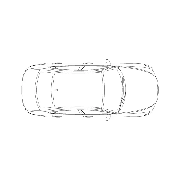
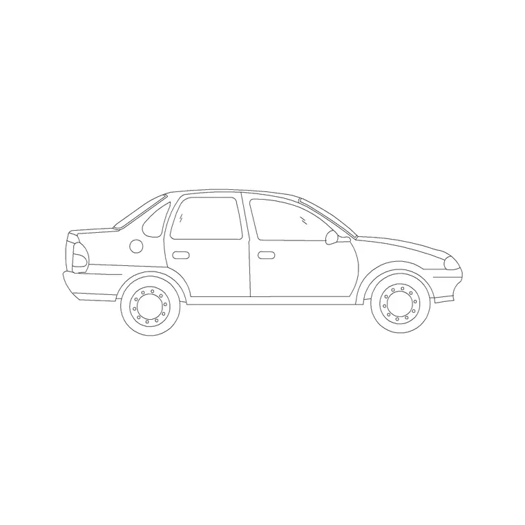
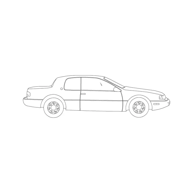
Before finalizing a gate or barrier opening width, it's worth placing one of our vehicle blocks directly into the plan at the opening, the compact sedan car or 2 door sedan car for a typical passenger vehicle check, or the BMW car front elevation dropped into a section view to confirm vertical clearance under a barrier arm or gate header if one exists. This is a fast way to catch an opening that reads fine as a dimension string but looks uncomfortably tight once there's a real vehicle silhouette sitting inside it, particularly at an angled or offset entrance where the usable clear width is less than the raw dimension suggests. Our paving blocks, paving-block-1 and paving-block-4, are useful for the finished surface either side of the control point, especially where a change in paving pattern is used deliberately to signal a vehicle control point ahead to an approaching driver.
What we do and don't carry
We don't currently carry dedicated boom barrier, bollard or gate CAD blocks as standalone downloads in the library, so if a specific barrier or bollard symbol is what you're after for a detailed drawing, that download isn't here yet. What our vehicle blocks are genuinely useful for, as covered above, is checking that the opening width and vertical clearance you've specified for a barrier, bollard run or gate actually works against a real vehicle footprint before the layout is finalized.
Common mistakes
- Positioning a barrier or gate right after a tight turn with no straight approach run - Spacing bollards for vehicle restriction without checking the gap against wheelchair and pushchair access where a pedestrian route also passes through - Specifying a barrier arm length without checking the fully raised clearance against an overhead obstruction - Sizing a gate for cars only, then discovering a delivery vehicle can't fit through the same opening - Choosing a fully automatic barrier without a manual override or backup power plan for a power outage at a busy entrance - Positioning an intercom, card reader or ANPR camera post inside the swing arc of a gate or the raised path of a barrier arm
Further reading
Questions
Frequently asked
How far apart should bollards be spaced?+
Where pedestrian access needs to be preserved, a clear gap of roughly 1 to 1.5 meters between bollards is a common guidance range, wide enough for a wheelchair or pushchair but too narrow for a car.
How wide should a vehicle gate be?+
A single lane gate for ordinary cars is commonly sized around 3 to 3.5 meters clear width, while a double lane or truck accessible gate is often 6 to 7 meters or more.
How long are standard boom barrier arms?+
Arms are typically available from around 3 meters up to 6 meters for a standard single lane span, with longer spans usually needing a support post or folding arm to avoid sagging.
Do you have boom barrier or bollard CAD blocks?+
Not currently as standalone downloads. Our vehicle blocks are useful for checking gate and barrier opening widths and clearances against a real vehicle footprint before finalizing the layout.
Free downloads from this article



Free CAD block library
Download the blocks from this article — free, no signup