An Acoustic Consultant's Guide to Downloading CAD Blocks
Free CAD blocks for acoustic layout studies, from workstation furniture to gym equipment, and how to scale them for reverberation checks.
Saumyajit MaityUpdated 11 June 20265 min read

Acoustics is a furniture and geometry problem as much as a materials one
It surprises people outside the field how much of an acoustic consultant's actual drafting work is furniture and room geometry rather than absorption coefficients and reverberation calculations, but the truth is you can't model how sound behaves in a space without first knowing what's actually in it, where the hard reflective surfaces sit relative to the soft absorptive ones, and how densely a room is packed. I've built enough acoustic layout studies to know that a properly scaled base plan with real furniture footprints saves genuine time once you get to the calculation stage, because you're not guessing at surface areas, you're measuring them off geometry that's already correct.
The catch here is that a lot of acoustic modelling software will happily accept whatever room area you feed it, correct or not, so the discipline of verifying your CAD geometry before it feeds a calculation matters more in this field than the calculation itself getting the formula right. I've caught more genuinely wrong recommendations traced back to a bad area figure than to a bad formula, which is a humbling thing to realise early in a career and a useful one to remember every time a new room gets set up in CAD.
Furniture blocks that matter for an acoustic study
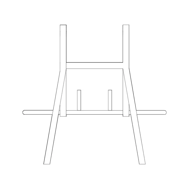
The office chair block from cadblockdwg.com is one I use constantly for open plan office acoustic studies, since seating density directly affects both absorption and the reverberation path length between workstations, and a realistic chair footprint, typically 550 to 650mm wide including the arms, lets you calculate actual occupied floor area rather than a rough estimate.
For gym and fitness spaces, which are genuinely difficult acoustic environments given hard flooring, high ceilings and impact noise from equipment, the gym equip block from Fitness & Sports gives you a realistic footprint to test layout against, useful both for the acoustic study itself and for coordinating with the fit out team on where absorptive treatment needs to go relative to the loudest equipment clusters. Outdoor noise mitigation is worth planning for too, and a row of pine elevation blocks from Trees & Plants along a site boundary is a genuinely useful way to represent a vegetation buffer in a plan, since dense planting is a recognised, if modest, contributor to perceived noise reduction along a boundary line, alongside whatever fencing or bunding a project is also relying on.
Room geometry blocks and why Building Symbols matters here
Wall assembly and door symbols from the Building Symbols category are genuinely useful in acoustic work beyond their obvious architectural role, since sound transmission class ratings are only meaningful when tied to a specific, correctly drawn wall assembly and door type in your plan, and a door symbol drawn to the wrong swing or the wrong leaf width can misrepresent the actual gap a sound path has to travel through.
I'll typically overlay these symbol blocks on my base plan early, before any furniture goes in, so the room's fixed acoustic boundaries are locked before I start populating it with the movable elements that furniture and equipment blocks represent, since it's much easier to catch a boundary problem, an undersized door leaf relative to its rated assembly for instance, before the room is full of furniture obscuring the wall lines.
Setting up a plan for reverberation and layout studies
Set your units to millimetres and work at 1:50 for a room level acoustic study, since that scale gives you enough resolution to place furniture accurately without the file becoming unwieldy. Once blocks are inserted, check total occupied floor area against your room's actual floor area, this ratio matters directly for occupancy based reverberation estimates, and a scale error here doesn't just look wrong on the drawing, it will throw off your actual acoustic calculation if you're pulling areas or counts directly off the CAD file rather than double checking them by hand.
I've made a habit of running that area check twice, once right after inserting the furniture and once again right before the numbers go into a calculation, since a lot can change in a drawing between the two moments on a live project with multiple people touching the same file.
Layering for coordination with the wider design team
Acoustic studies rarely stand alone, they need to sit against the architect's base plan and often the MEP layout too, since ductwork and equipment are frequently the actual noise source you're mitigating for. I bring the architectural plan in as an XREF and build furniture and treatment call outs on a separate layer, something like ACOU-FURN and ACOU-TREAT, so the acoustic drawing updates automatically if the architect revises the room layout, and so a treatment recommendation, an absorptive panel location for instance, is clearly distinguishable from the furniture blocks it sits near.
This coordination matters especially on a fast moving fit out project, where the architectural layout can still be shifting even as the acoustic report is being finalised, and an XREF based workflow means your recommendations stay tied to the current room shape rather than a snapshot that's already gone stale.
A couple of things worth double checking before issuing a report
Make sure any furniture block you've resized to fit a tight room hasn't lost its true scale in the process, since a stretched block will throw off any area or clearance measurement pulled from it for your calculations. And remember that a plan view, which is [orthographic projection](https://en.wikipedia.org/wiki/Orthographic_projection) by definition, can't show ceiling height or a suspended acoustic treatment on its own, so for anything involving overhead absorption or diffusion, pair your plan with a section drawing, since acoustic performance depends on the full three dimensional volume of a room, not just its floor area.
Any decent [technical drawing](https://en.wikipedia.org/wiki/Technical_drawing) covering an acoustic study should carry both views, because the plan alone tells only half the story a client actually needs to sign off on, and a report that only shows plan geometry tends to invite more follow up questions than one that pairs it with a clear section from the outset. I'll also attach a short note on the drawing itself flagging which dimensions came from a verified CAD measurement versus a site estimate, since a client reading the report later benefits from knowing exactly how much confidence to place in each number.
Further reading
Questions
Frequently asked
What CAD blocks are useful for an office acoustic study?+
Office chair blocks for occupied floor area and seating density calculations, plus wall and door symbol blocks from Building Symbols to accurately represent sound transmission boundaries in the room.
Do CAD blocks affect the accuracy of a reverberation calculation?+
Indirectly, yes. If you're pulling occupied floor area or furniture counts directly off the CAD file, a block inserted at the wrong scale will feed a wrong number into your calculation, so always verify block scale before relying on measurements taken from it.
Should an acoustic study use plan views alone or plan and section together?+
Both, ideally. A plan view alone can't represent ceiling height or overhead treatment, and acoustic performance depends on a room's full volume, not just its floor area, so pairing a plan with a section is standard practice for anything beyond a rough layout check.
Free downloads from this article

Free CAD block library
Download the blocks from this article — free, no signup