Accessible parking bay dimensions and matching CAD blocks
Typical accessible parking bay and access aisle widths, how they differ from standard bays, and how to lay them out in a CAD site plan.
Sumana KumarUpdated 1 May 20266 min read
It's the aisle, not just the bay, that makes a space accessible
An accessible parking bay isn't just a wider painted rectangle, it's a bay plus an adjacent access aisle, and the aisle is genuinely the part that does the work, because it's the space someone needs to lower a ramp, transfer into a wheelchair, or open a door fully alongside the vehicle without stepping into the drive lane. I've reviewed site plans where the bay itself was sized generously but the access aisle was squeezed to almost nothing to fit an extra standard space in, and that's exactly the kind of shortcut that fails inspection and, more importantly, fails the person actually trying to use the space.
So when you're laying out an accessible lot, think of it as two zones that have to be drawn and dimensioned separately, a vehicle bay and an access aisle, rather than one wide space, because most codes check them individually.
The dimension ranges that show up most often
Figures vary by jurisdiction, so treat these as working ranges to confirm against your local code rather than fixed numbers. Standard accessible bays are typically in the 2400 to 2600mm (roughly 8 to 8.5 feet) width range, similar to or slightly wider than a standard bay, with an adjacent access aisle usually falling somewhere around 1200 to 1500mm wide. Van-accessible spaces, meant to accommodate a side-loading ramp or lift, usually need a noticeably wider aisle, often in the range of 2000 to 2400mm, since a deployed ramp needs considerably more room than a car door swing.
Most codes also set a minimum count of accessible bays relative to total lot size on a sliding scale, and a minimum number of those bays as van-accessible specifically, so it's worth checking the ratio requirement early rather than adding accessible bays as an afterthought once the rest of the lot is laid out.
It's also worth checking whether your local code counts van-accessible and standard accessible bays separately toward the total required count, or whether van-accessible bays satisfy both requirements at once, since some jurisdictions treat them differently and a schedule that assumes one interpretation can come up short under the other.
Laying it out in a CAD site plan
What I actually do is set up the bay and aisle as a single reusable block once I've confirmed the local dimensions, with the bay, the aisle, and the required signage location all included as one unit, so I can copy it around the lot without redrawing the same geometry five or six times. Keeping the aisle striping on its own layer makes it easy to toggle for different presentation drawings, and it also makes it much faster to spot, at a glance, whether every accessible bay in the lot actually has its aisle drawn, since a missing aisle on one bay out of a dozen is an easy thing to lose in a busy site plan.
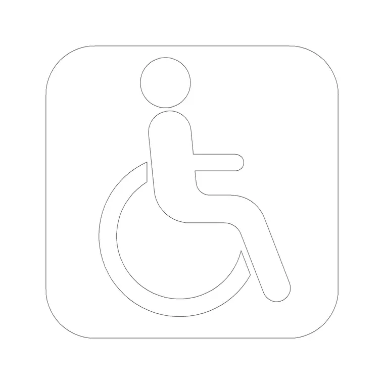
I also always place a wheelchair figure or symbol block at one or two of the bays, mainly so reviewers and clients can see the intended use at a glance rather than reading a dimension string and a code reference to understand what the space is for.
I'll also tag each accessible bay with its own callout number tied back to a small schedule on the same sheet, van accessible or standard accessible, rather than relying on the drawing reader to count symbols across a busy lot, since a reviewer checking compliance is usually working from that count against the code ratio requirement and a clear schedule saves them from recounting bays by eye across a large site plan. On a bigger lot with accessible bays spread across several rows, it's worth double checking that your block insertions haven't drifted from true north or gotten mirrored accidentally during a copy operation, since a mirrored aisle can end up on the wrong side of the bay relative to the vehicle, which defeats the purpose of the aisle even though the bay and aisle widths both still measure correctly on paper.
Slope and surface, the part that isn't about width at all
Width and aisle dimensions get most of the attention, but accessible bays also typically carry a maximum surface slope requirement in most codes, often capped fairly low, commonly cited in the range of 1:48 to 1:50 maximum in any direction, which is far flatter than a standard parking surface is usually graded to for drainage. This is a civil and grading concern as much as a layout concern, so if you're doing the site plan without a civil engineer's grading drawing in hand, flag the accessible bays specifically for a slope check rather than assuming standard lot grading will pass.
A bay that's dimensionally correct but sits on a 1:20 grade for drainage purposes will still fail an accessibility review, and it's a mistake that only shows up once someone actually checks the grading plan against the parking layout, which is worth doing before the lot goes to construction documents.
Connecting the bay to the building
An accessible bay that isn't connected to an accessible route into the building doesn't actually accomplish much, so the layout check doesn't stop at the aisle edge, it continues through the curb ramp or flush transition, along the accessible route, and up to the building entrance. This is the point where it's worth cross-checking your parking layout against ramp gradient standards for any curb transition, and against clear door opening width at the entrance itself, since all three are really one continuous accessible path and get reviewed that way even when they're drawn on separate sheets.
Accessible bays in multi-level or structured parking
Structured parking decks add a layer most surface lots don't have to deal with, vertical clearance for a raised roof or a wheelchair lift, and ramp gradients between levels that need to meet the same accessible slope limits as any other ramp on the site. Accessible bays in a parking structure are usually placed on the level closest to the accessible entrance or lift lobby specifically to minimize the distance a wheelchair user has to travel through the structure, rather than distributed evenly across every level the way standard bays might be. If you're laying out a multi-level structure, it's worth confirming the accessible bay count and location requirement separately for each level rather than assuming the building-wide ratio can be met by clustering every accessible bay on the ground floor alone, since several codes specifically require distribution across levels once a structure passes a certain size.
Blocks and categories to pull from
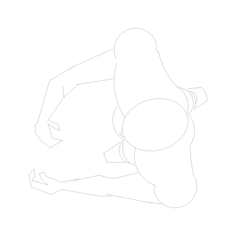
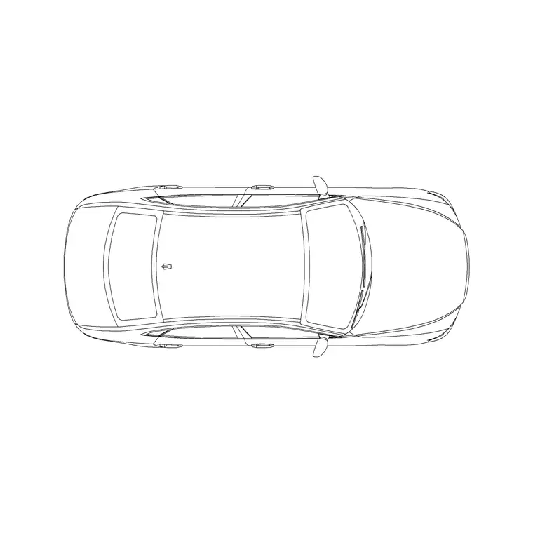
The wheel-chair-accessible and wheel-chair-accessible-2 blocks under building-symbols work well as the symbol placed within the bay itself, and a human-figure-disable block is useful further along the route to show the same figure approaching the building, which helps tie the whole accessible path together visually across a site plan. If your site plan also needs standard vehicle footprints for the rest of the lot, the vehicles category on this site has a range of free DWG blocks to fill out the remaining bays without redrawing car outlines by hand.
Further reading
Questions
Frequently asked
How wide is a typical accessible parking bay?+
Standard accessible bays are commonly in the 2400 to 2600mm range, with an adjacent access aisle usually around 1200 to 1500mm, though van-accessible spaces typically need a wider aisle, often 2000mm or more. Confirm the exact figures against your local code.
Do accessible parking bays have a slope requirement?+
Yes, most codes cap the surface slope quite low, often around 1:48 to 1:50 maximum in any direction, which is flatter than typical drainage grading, so it's worth checking the grading plan specifically for accessible bays.
What CAD blocks help show an accessible parking layout?+
The wheel-chair-accessible blocks under building-symbols work well as the bay symbol, and pairing them with a human-figure-disable block along the route to the entrance helps communicate the full accessible path on a site plan.
Free downloads from this article

Free CAD block library
Download the blocks from this article — free, no signup