Using DWG CAD Blocks in Civil 3D: What You Need to Know
How ordinary 2D DWG blocks behave inside Civil 3D, what site plans genuinely need from a block library, and what Civil 3D handles as its own objects.
Saumyajit MaityUpdated 7 June 202610 min read
Civil 3D is still AutoCAD underneath
The first thing worth settling is that Civil 3D is built on the same core platform as plain AutoCAD, so basic block behaviour, INSERT, scale, rotation, layer assignment, works identically whether you are inside a pure architectural drawing or a full civil site plan. If you already know how to insert a block cleanly in AutoCAD, you already know how to do it in Civil 3D, nothing about the block insertion mechanism itself changes.
What does change is the surrounding context, a site plan carries concerns that a floor plan simply does not, real world coordinate systems, large scale sheets, and a whole layer of civil specific objects that are not blocks at all, and understanding that boundary is the actual useful part of this topic.
I have watched people new to civil work spend real time hunting through a general block library for something that was never going to be there, a manhole cover, a catch basin symbol, a specific pipe fitting, when the actual answer was that Civil 3D generates that content from its own parts lists and pipe network tools rather than from inserted blocks at all. Knowing where that line sits before you start searching saves the wasted search entirely.
What inserts cleanly without a second thought
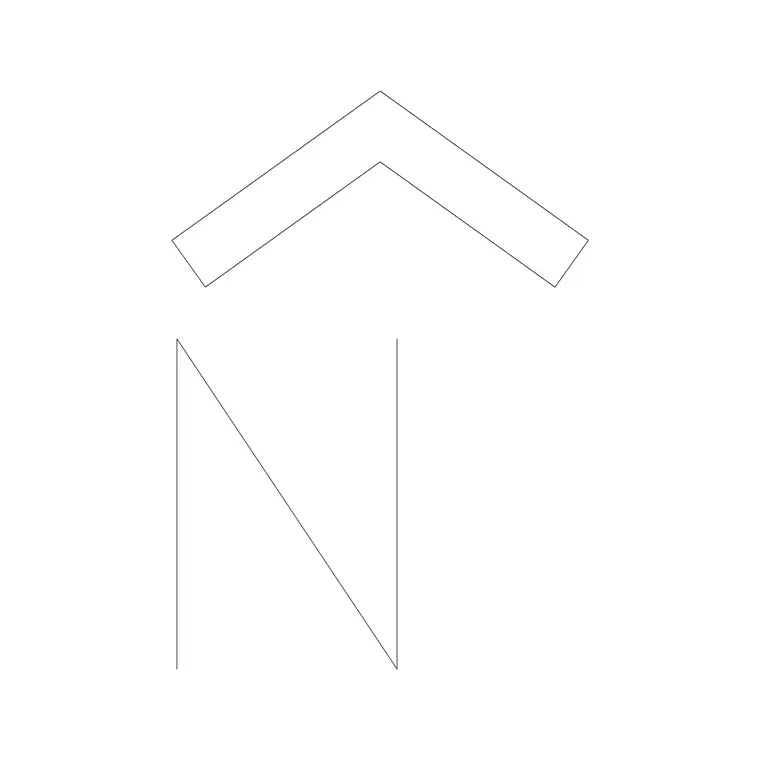
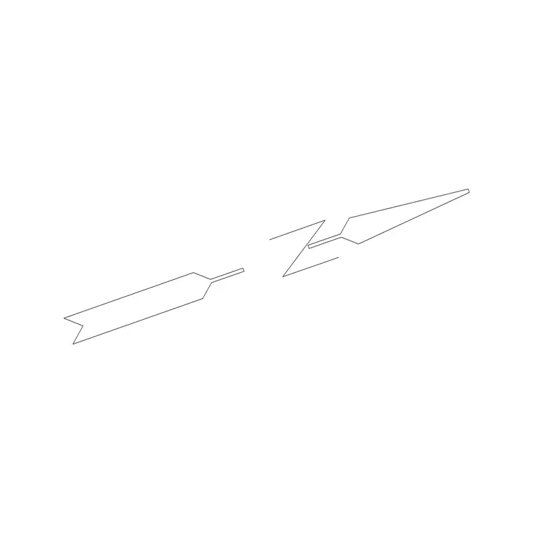
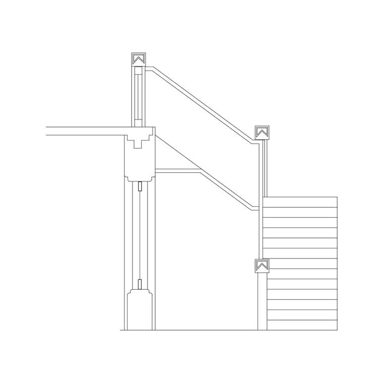
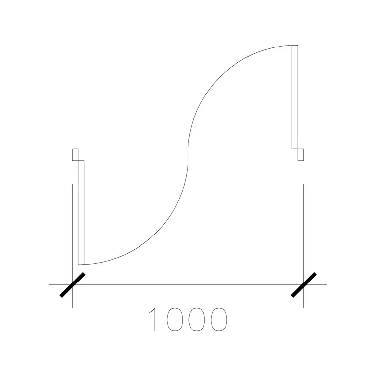
Plain 2D symbol and reference blocks slot into a Civil 3D site plan exactly the way they would into any AutoCAD drawing. A north arrow like North Arrow 1 or North Arrow, people and site furniture for scale, paving patterns, trees along a boundary, and even architectural elements like a door or window plan for a building footprint detail, all insert and behave normally, since Civil 3D treats them as ordinary block references regardless of what civil specific tools sit alongside them in the same file.
This is the category most people actually need when they reach for a general purpose block library on a civil project, the annotation and site dressing content that every plan needs, north indication, scale figures, planting, paving, rather than anything engineering specific.
A door or window plan earns its place on a civil sheet specifically at the detail level, a building footprint plan showing entrance locations relative to an access road, or a small scale detail callout referencing a specific entrance condition, rather than as part of the main site engineering content itself. Treat these architectural blocks as supporting detail on an otherwise civil focused sheet, not as the primary content of the drawing.
What Civil 3D handles as its own objects, not blocks
Where things genuinely diverge is everything Civil 3D adds specifically for civil engineering work, parcels, alignments, profiles, corridors, surfaces built from survey data, and pipe networks. These are native Civil 3D objects with their own styles, behaviour, and editing tools, not block references, and no general purpose block library, including this one, attempts to replace them, because they simply are not the same kind of thing as a static drafting symbol.
Worth being explicit here since it avoids a common false expectation, this catalogue does not carry manholes, pipe network components, valves, or similar MEP and civil engineering fixtures. If your project needs those specific objects, they belong in Civil 3D's own parts lists and object styles, not in a general architectural and interior block library like this one, and it is better to know that upfront than to search this catalogue expecting something it was never built to provide.
This catalogue does carry a genuinely deep well of general architecture, interior, and landscape content, well over 500 furniture products, close to 900 tree and plant blocks for site landscaping, and site adjacent categories like paving and outdoor furnishing, so for the parts of a civil site plan that overlap with architectural presentation, planting layout, hardscape patterns, entrance detailing, there is real, substantial material here. The honest boundary is purely around the engineering objects proper, pipes, structures, and network components, which sit outside what any static block library, this one included, is designed to provide.
A concrete instance of exactly this boundary showing up
A concrete instance of exactly this boundary showing up, on a site plan I was helping put together, someone had spent a good twenty minutes scrolling through a general symbol library looking for a stormwater catch basin block to drop into a drainage layout, understandably assuming it would exist somewhere the same way a door or window plan does. It never was going to, because a catch basin in Civil 3D is a structure object generated from the Pipe Networks tools, complete with its own rim elevation, invert, and connection to whatever pipe run feeds it, none of which a static 2D block could represent even if one existed, since a block simply has no elevation data or connectivity logic built into it at all.
The fix, once that clicked, was placing the structure properly through Civil 3D's own Pipe Network creation tools instead, which took a few minutes once the right tool was found, considerably faster than the symbol search that preceded it, and produced something that actually carried real elevation and connectivity data through to the profile view later in the same project, which a dropped-in block never could have done regardless of how visually similar it might have looked sitting on the plan.
The broader habit worth taking from that, whenever a site plan needs something that sounds like it should be a simple symbol, a catch basin, a valve, a hydrant, it is worth pausing for a second and asking whether the object actually needs to carry engineering data, elevation, connectivity, pipe size, before assuming a quick symbol search is the right approach at all. If the answer is yes, it almost certainly belongs in Civil 3D's own object tools rather than in any general block library, this one included, and going straight to those tools from the outset saves the exact kind of wasted search that ate up time on that drainage layout in the first place.
Coordinate systems and why scale needs extra attention
Site plans typically live at a much larger real world extent than a building floor plan, often plotted at scales like 1:200 or 1:500 rather than the 1:50 or 1:100 common on architectural sheets. A symbol block inserted at whatever default scale it was drawn at can end up looking microscopic or absurdly oversized once the sheet's actual plot scale is applied, the same underlying issue as sizing text correctly at a given drawing scale, just applied to a whole inserted symbol rather than a line of text.
Before inserting any annotation block into a civil sheet, check what scale that viewport or layout will actually plot at, and size or scale the inserted block relative to that figure rather than trusting whatever the block happened to be drawn at when someone else built it.
The practical fix is the same formula that governs text height at a given scale, decide the target plotted size for the symbol on paper, then scale the inserted block by the ratio between that target and its as drawn size, rather than inserting at a default scale factor of one and hoping it happens to look right. A north arrow that reads perfectly at 1:100 will look almost invisible at 1:500 unless it is deliberately scaled up to compensate, the geometry itself has not changed, only how much of the real world one drawing unit now represents.
Layer standards tend to be stricter on civil projects
Civil engineering offices frequently work to a formal layer naming standard, sometimes a recognised national standard, sometimes an in house convention, with prefixes indicating discipline and object type. A block inserted straight off its original layer, whatever that happened to be named in the source file, can quietly violate that standard even though nothing looks visually wrong.
Good general practice, and it applies just as much outside civil work, is keeping inserted block geometry on a neutral layer, commonly layer 0, so the block picks up whatever layer property you assign it on insertion rather than carrying an arbitrary layer name into a drawing that has its own naming rules. This is a small habit that saves real cleanup time on a project with strict CAD standards enforcement.
It is worth running this check specifically before a drawing goes to an external reviewer or authority, since a civil submission failing on a formatting technicality, wrong layer names on inserted content, rather than on the actual design is an entirely avoidable, faintly embarrassing outcome. A quick layer audit across the whole sheet before submission catches this category of issue in minutes rather than after a review comment forces a resubmission.
Paper space viewport scale and inserted symbols
Civil 3D site plans commonly build model space at true, real world coordinates and then present multiple viewports at different scales in paper space, an overview key plan alongside a detailed working sheet, for instance. A symbol block that reads correctly in one viewport can look wrong in another purely because of that viewport's own zoom factor, which is a scale interaction worth checking specifically rather than assuming a single insertion works everywhere at once.
Lock each viewport's scale once it is set, and verify annotation sized content, including any inserted symbol blocks, actually reads at a sensible size in every viewport it appears in on the finished sheet, not just the one you happened to be looking at while you placed it.
A quick habit that catches most viewport scale surprises early, zoom to actual paper space and glance across every viewport on the sheet at once rather than tabbing into each one individually, since inconsistent symbol sizing between two viewports on the same page is far more obvious side by side than it is checking one viewport at a time in isolation.
External references and file size on civil projects
Civil 3D projects frequently build up from external references, a survey base, a topographic file, sometimes layered several xrefs deep. Inserting a handful of ordinary static blocks into that structure does not require any special handling, they behave the same as in any xref'd drawing.
Where it is worth some care is at scale, civil base files tend to already be large given the volume of survey and terrain data involved, so binding or exploding a large number of complex blocks directly into an already heavy xref'd base is worth thinking about for performance, though a handful of simple 2D symbols, the kind covered here, adds negligible weight regardless.
A related habit worth keeping, insert blocks into the specific drawing that will actually carry them in the final set, rather than into the xref'd base itself, since edits made directly to a shared base file ripple out to every drawing referencing it, which is rarely what you want for something as local as a single site plan's north arrow placement or planting layout. Keep the base clean and stable, and let individual sheet drawings carry their own annotation and dressing content on top of it.
This discipline scales well past a single site plan too, once several sheet drawings reference the same base, keeping local dressing content local means a change to one sheet's planting layout or north arrow position never accidentally propagates to a sheet where nobody intended it, which is exactly the kind of quiet cross project bug that a shared xref structure can otherwise introduce without anyone noticing until a review catches it.
A practical checklist for a civil site plan
- Confirm what the sheet will actually plot at before sizing any inserted symbol block. - Insert general purpose blocks, north arrows, people, trees, paving, doors, and windows for building detail callouts, exactly as you would in plain AutoCAD. - Do not expect this or any general block library to carry civil specific engineering objects, parcels, pipe networks, and similar content are native Civil 3D objects, not blocks. - Keep inserted geometry on a neutral layer to respect whatever layer standard the project follows. - Verify annotation sized content in every paper space viewport it appears in, not just the first one you check.
Handled this way, a general purpose 2D block library slots into a civil workflow exactly where it belongs, dressing and annotating the plan, while the genuinely civil specific work stays in Civil 3D's own dedicated tools.
The overall pattern worth internalising, a civil site plan is really two layers of content stacked together, the engineering layer, surfaces, alignments, pipe networks, built from survey data using Civil 3D's own dedicated tools, and the presentation layer, symbols, planting, paving, scale figures, that reads much closer to an ordinary architectural drawing and is exactly where a general block library earns its keep. Keep that distinction clear and you will rarely find yourself hunting a block library for something that was only ever going to come from Civil 3D's own object styles.
Further reading
Questions
Frequently asked
Will a simple 2D block from a DWG library work in Civil 3D?+
Yes. Insertion behaves identically to plain AutoCAD, since Civil 3D is built on the same core platform and treats a block reference the same way regardless of what civil specific tools sit alongside it.
Does this site have civil engineering objects like manholes or pipe network parts?+
No. The catalogue is genuinely zero on manholes, valves, and similar MEP or civil engineering fixtures. It focuses on general architectural, interior, and site symbol content, doors, windows, stairs, trees, paving, and north arrows.
What scale should a north arrow be inserted at on a site plan?+
There is no fixed universal size. Check the actual plot scale of the sheet or viewport it will appear in and size the block relative to that, the same principle that applies to sizing text at a given drawing scale.
Do I need Civil 3D specifically, or does plain AutoCAD work the same way for block insertion?+
For basic block insertion, plain AutoCAD behaves identically, since Civil 3D adds civil specific objects on top of the same core platform rather than changing how ordinary blocks work.
Free downloads from this article

Free CAD block library
Download the blocks from this article — free, no signup