Turning a 2D CAD Block Into a Revit Family
Why a DWG block and a Revit family are fundamentally different objects, and the honest workflow for tracing a 2D CAD block into a parametric family.
Sumana KumarUpdated 9 April 202610 min read
The request that sounds simpler than it is
I have had this exact request more than once, someone finds a door or window block they like in a DWG library and asks for the Revit version, expecting it to essentially be the same file in a different wrapper. It is not, and it is worth being upfront about that before diving into workflow, because a DWG block and a Revit family are genuinely different kinds of object, not two file formats of the same thing.
Understanding that difference up front saves real time, because it changes what you should actually expect to get out of converting one into the other.
The underlying reason this confusion happens so often is that both file types end up looking identical on screen, a door is a door visually whether it lives inside a DWG or a Revit family, and that visual similarity hides just how differently the two are actually structured underneath. The moment you try to schedule the object, tag it, or change its type and expect the geometry to update automatically, the gap between the two becomes obvious very fast.
What a Revit family actually is, versus a block
A DWG block is static geometry, lines, arcs, and text, saved under a single name so it can be inserted repeatedly. It carries no built in intelligence about what it represents, an AutoCAD block does not know it is a door any more than it knows it is a chair, it is simply geometry.
A Revit family is a fundamentally different kind of object, part of Building Information Modeling rather than plain drafting. It belongs to a category, doors, furniture, windows, carries parameters like width and height that can drive its geometry, supports multiple types within one family, and feeds directly into schedules, tags, and quantity takeoffs elsewhere in the model. That parametric intelligence is the entire value proposition of a family, and it is exactly the part that a static DWG block simply does not have and cannot be automatically converted into.
This matters practically the moment a project reaches quantity takeoff or a door and window schedule sheet, since a scheduled count of every door type and its width comes directly out of family parameters, not out of counting inserted blocks by hand. A DWG based drawing can absolutely be tallied manually, or through AutoCAD's own block counting tools, but it will never feed a live Revit schedule the way a proper family instance does, that connection only exists once the object is genuinely a family, not a lookalike.
It is worth clarifying that this is not a criticism of DWG as a format, it was never built to carry that kind of database aware intelligence in the first place, plain drafting geometry and a parametric BIM object are simply solving different problems, and expecting one to behave like the other is where the frustration usually comes from rather than from any actual shortfall in either format.
Two honest paths forward, not one
Given that gap, there are really two legitimate ways to use a DWG block in a Revit context, and it is worth choosing deliberately rather than defaulting to whichever one you happen to try first. The first path treats the DWG purely as a 2D reference, linked or imported into the Family Editor and traced over to build genuine native Revit geometry and parameters on top of it. The second path keeps the DWG as a 2D linked CAD symbol used directly for annotation or detail purposes, accepting that it will never behave like a scheduled, parametric family and simply is not trying to.
The first path is real modelling work with a real payoff, a genuine family. The second path is faster but honest about its limits, a 2D symbol, not a family, however you dress it up.
Which path makes sense depends heavily on how the object will actually be used downstream. If nobody ever needs to schedule it, tag it by type, or vary its size across the project, the linked CAD symbol path is a perfectly legitimate, much faster choice, and forcing every single reference detail through a full family build is often wasted effort. Reserve the tracing path specifically for objects that genuinely need to behave as first class, schedulable elements in the model.
Walking through the tracing path step by step
Start from the correct family template for the category you are building, a door template for a door, a furniture template for a piece of furniture, since the template sets up the right category, view templates, and reference planes for that object type from the outset. Inside the Family Editor, use Insert, Import CAD to bring in the DWG block at the correct scale, positioned relative to the family's origin and existing reference planes.
Snap new reference planes to key points on the imported linework, opening width, frame thickness, whatever dimensions the family needs to parametrise, then draw genuine native Revit geometry over that reference rather than relying on the imported CAD lines themselves to display in the finished family. Once the native geometry is complete and correctly constrained to those reference planes, delete or hide the imported CAD link, it has done its job as a tracing guide and should not remain as visible geometry in the finished family.
A habit worth building here, lock the imported CAD geometry immediately after positioning it, before you start tracing, so an accidental click and drag during modelling does not shift your reference out from under the work you have already done. It is a small step that has saved me from redoing a reference plane alignment more than once after an absent minded drag moved the underlying import by a few millimetres without me noticing right away.
The most common mistake that breaks a traced family later
The single most common mistake I see when someone traces a DWG block into a family for the first time isn't in the tracing itself, it's forgetting to lock the new geometry's dimensions to the reference planes that are meant to drive it, so the shape looks correct the moment you finish drawing it but then does something strange, or nothing at all, the first time anyone actually flexes the family by changing a type parameter. Revit families work by having geometry genuinely constrained to reference planes through dimensions that are then associated with parameters, not by geometry simply sitting near a reference plane and looking aligned, and skipping that association step is an easy thing to do when you are focused on getting the shape to look right rather than on making it behave right.
The way I catch this before it becomes a problem on a live project is flexing the family deliberately before ever considering it finished, opening Family Types, changing the width or height parameter to something noticeably different from the default, and watching what actually happens to the geometry in the preview. If everything moves the way it should, door leaf, frame, swing arc, scaling correctly with the new dimension, the constraints are genuinely working. If something stays put while everything else moves, or the geometry distorts in a way that clearly is not intended, that is exactly the reference plane and dimension association that needs fixing before the family goes anywhere near a real project.
This matters more than it might seem worth the extra step, because a family that has never been flexed and tested can sit in a project library looking completely correct at its default size for a long stretch of time, right up until someone on a later project actually needs a different width and discovers the geometry does not respond the way a genuinely parametric family should. Catching that at the point of building the family, rather than months later on someone else's project, is the entire reason flexing a family before considering it done deserves to be treated as a mandatory last step rather than an optional nicety.
Units and scale traps worth checking before you start
DWG content, including everything in this catalogue, is typically drawn in millimetres, while Revit family templates, particularly in regions that default to imperial units, can be set up expecting feet and inches. The Import CAD dialog has its own unit setting, and assuming it will guess correctly rather than checking it explicitly is exactly how a correctly proportioned door block ends up traced at completely the wrong physical size inside the family.
Verify the import units deliberately every time, especially the first time you bring a metric DWG into an imperial family template, since this single setting is responsible for more silently wrong family geometry than any other step in the process.
What you gain, and what you genuinely lose
Doing the tracing work properly gets you full parametric behaviour, types that vary by size, parameters that drive schedules, tags that read correctly in a door or window schedule sheet, and geometry that responds sensibly if someone later changes a type's dimensions. What you lose is whatever fine surface detail existed only as linework in the original DWG and was never explicitly rebuilt as native geometry, since tracing captures what you deliberately model, not everything that happened to be present in the reference.
For a simple object, a straightforward door or window swing, the tracing effort is genuinely short, an afternoon at most for someone reasonably comfortable in the Family Editor. For something with a lot of surface detail, an ornate piece of furniture with many visible components, expect meaningfully more modelling time, since every visible feature has to be deliberately rebuilt as real geometry rather than inherited automatically from the reference.
A middle ground that a lot of offices land on for lower priority content, model a simplified representation carrying only the parameters actually needed for scheduling and general plan graphics, and skip reproducing every fine surface detail that will realistically only ever be seen in a rendering rather than a construction document. A family does not need to be visually perfect to be useful, it needs to be dimensionally correct and to schedule properly, and being clear about which of those two goals actually matters for a given object saves real modelling time across a project with many types to build.
Where a DWG library like this one genuinely fits into that workflow
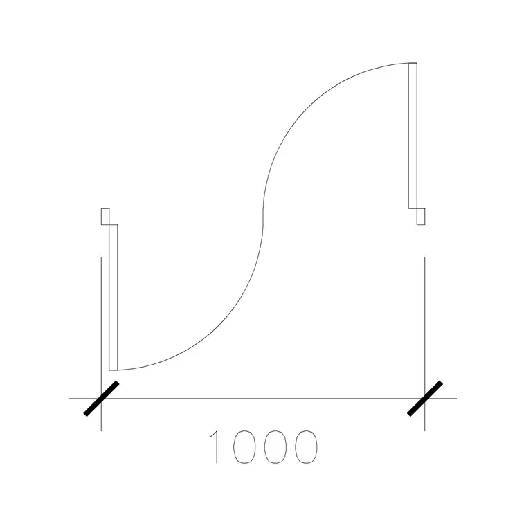
Being straightforward about what this site actually offers, the catalogue here is DWG format, there is no direct RFA family download, and there should not be an expectation that one exists. What a real, accurately proportioned DWG block does provide is a fast, reliable tracing reference, a door plan like 1000 Mm Door Type 1 or a window plan like Window Plan 1 gives you a correct real world opening width to snap reference planes to, rather than guessing a dimension from memory or a photograph.
That is a genuinely useful head start on the family building process described above, it just is not, and should not be mistaken for, the finished family itself. Treat the download as your accurate starting reference, and the modelling inside Revit as the separate, necessary step that actually produces the parametric object.
This is also where checking a block's dimensions against real world standards before tracing pays off, a door width should sit within the kind of realistic range you would expect for its stated use, and a window plan should reflect proportions that actually correspond to how that opening would be built, rather than an arbitrary shape that merely looks plausible. Verifying that before you commit reference planes to specific dimensions avoids baking an unrealistic size into a family that later gets used across an entire project.
A quick sanity check worth running on any traced dimension, compare it against the millimetre to inch and general sizing conventions covered elsewhere on this site, a door width that converts to a sensible, ordinary inch figure is far more likely to be correct than one that lands on an oddly specific, non standard number, and that kind of quick cross check catches a mistraced dimension well before it reaches a live project schedule.
A short checklist before you start tracing
- Pick the correct category template for what you are building, do not start from a generic template and reassign category later. - Import the DWG at the correct, verified scale, checking units explicitly rather than assuming. - Snap reference planes to the dimensions that actually need to parametrise, not every visible line. - Model native geometry over the reference, then hide or delete the imported CAD link once the tracing is done. - Test at least two different type sizes before considering the family finished, to confirm parameters actually drive the geometry the way you intended.
Follow that order and a 2D CAD block becomes a genuinely useful starting point for a proper parametric family, rather than a source of false expectations about what conversion can automatically deliver.
Further reading
Questions
Frequently asked
Can I just import a DWG block directly as a working Revit family?+
No. Importing brings it in as flat 2D or 3D CAD geometry with zero parametric behaviour, not a true family. It needs to be traced and rebuilt as native Revit geometry to actually function as one.
Does this site offer Revit family (RFA) downloads?+
No, the catalogue is DWG format only. A DWG door or window block works well as an accurate reference to trace from when building a native family, but it is not an RFA file itself.
Should I link or import the DWG into the Family Editor?+
Either can work as a tracing reference, Import CAD is more commonly used inside the Family Editor since it keeps the reference geometry contained within that specific family rather than a separate link the wider project has to manage.
How long does converting a simple 2D block into a family actually take?+
It varies with complexity. A straightforward door or window swing is typically a short job once traced correctly, while a detailed piece of furniture with many visible components takes meaningfully longer since every feature has to be rebuilt as real geometry.
Free downloads from this article


Free CAD block library
Download the blocks from this article — free, no signup