Millimetre to Inch Conversion for CAD Block Sizing
A practical millimetre to inch reference table for CAD block sizing, plus why downloaded metric blocks sometimes insert at the wrong scale.
Sumana KumarUpdated 3 May 202611 min read
The insert that looked laughably wrong at first glance
I still remember the first time I inserted a metric block into a drawing template set up in inches and watched it appear roughly forty times too big, filling half the screen where a small fitting should have sat neatly in a corner. Nothing was broken, the block itself was fine, the issue was purely a units mismatch between the file I was inserting and the file I was inserting it into, and this exact scenario is common enough that it is worth understanding the conversion properly rather than just rescaling by trial and error every time it happens.
Most CAD block libraries, including this one, are drawn in millimetres, since that is the standard working unit across most of the world's architectural and interior drafting. Plenty of drafters, particularly across parts of North America, still work primarily in inches and feet, and that gap is where a reference table earns its keep.
The scenario repeats often enough to be worth naming plainly, an office working comfortably in feet and inches pulls in a metric reference block, a door, a piece of furniture, a fixture, and needs to know both what its real size actually is in familiar units, and whether it will insert into their drawing at the correct scale without manual correction. Both of those questions have the same underlying answer, the exact 25.4 millimetre conversion factor, just applied slightly differently depending on which one you are actually solving.
The conversion itself, and why it is exact, not approximate
One inch equals exactly 25.4 millimetres. This is not a rounded approximation, it has been the internationally agreed exact definition of the inch since 1959, so there is no precision lost converting between the two units, only rounding introduced afterward if you choose to display a converted figure to fewer decimal places than the maths actually supports.
To go from millimetres to inches, divide by 25.4. To go from inches to millimetres, multiply by 25.4. Committing that single number to memory covers the vast majority of CAD sizing conversions you will ever need, everything else in this post is really just that one multiplication applied repeatedly to figures that come up often in practice.
A useful mental shortcut for rough estimates without reaching for a calculator, four millimetres is close to a sixth of an inch, and a hundred millimetres is close to four inches, both convenient enough for a fast sanity check in your head while reviewing a drawing, though for anything that actually matters on a construction document, always fall back to the exact 25.4 figure rather than trusting a rounded mental shortcut for a final dimension.
Why this specifically bites when inserting a downloaded block
AutoCAD has a system variable, INSUNITS, that records what unit a given drawing is set up to represent, and when both the source block file and the destination drawing have this set correctly, AutoCAD automatically scales an inserted block to compensate for any unit difference between them, so a millimetre drawn block dropped into an inch based drawing should, in principle, resize itself correctly on the way in.
The common failure is either file having INSUNITS set to Unitless, which breaks that automatic scaling entirely, since AutoCAD then has no declared unit to convert from or to and simply inserts the raw numeric values unchanged. This is almost always the actual cause behind a block that inserts at a wildly wrong scale, not a fault in the block itself.
A second, less common but still real cause, both files have a valid, correctly set INSUNITS value, but they simply disagree, one genuinely set to millimetres, the other genuinely set to inches, in which case AutoCAD's automatic scaling actually does its job correctly and the block lands at the right real world size, just displayed relative to a different base unit than whichever one you were mentally expecting. In that situation the block is not wrongly scaled at all, it is your own expectation of what number you should see that needs adjusting, worth ruling out before assuming something is actually broken.
A reference table for common CAD door widths
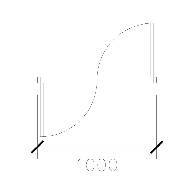
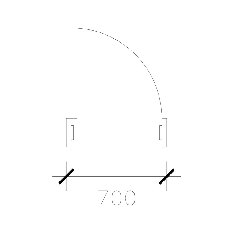
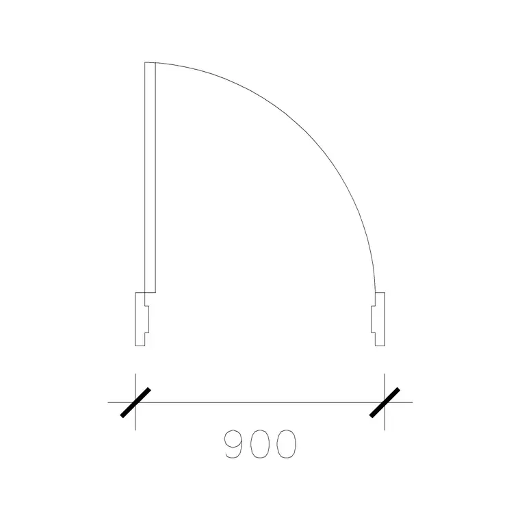
Door blocks are a good place to build intuition for this conversion, since they are commonly named directly by their width in millimetres, and this catalogue's doors category runs to genuine variety across that range. Working from real widths represented in the doors library here, converted using the exact 25.4 millimetre figure:
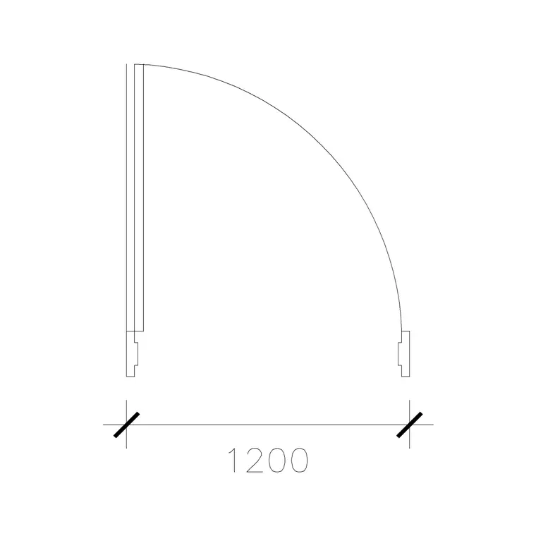
- 700 mm is approximately 27.6 inches - 750 mm is approximately 29.5 inches - 800 mm is approximately 31.5 inches - 850 mm is approximately 33.5 inches - 900 mm is approximately 35.4 inches - 1000 mm, the width of a block like 1000 Mm Door Type 1, is approximately 39.4 inches - 1200 mm is approximately 47.2 inches - 1500 mm, a wider double leaf configuration, is approximately 59.1 inches - 1800 mm, at the larger end of a double door opening, is approximately 70.9 inches
These are rounded to one decimal place for readability, the underlying maths is exact division by 25.4, so recompute to more decimal places yourself if a specific project needs tighter precision than shown here.
The wider point this table is meant to illustrate, real product widths in this catalogue's doors category do not land on tidy round inch figures once converted, which is exactly what you would expect from content designed around metric convention rather than imperial, so treat a converted figure as informational for cross checking rather than assuming it should come out to a clean number, an office working primarily in inches would typically round a specified opening to the nearest practical imperial figure during actual construction regardless of what the metric source drawing states precisely.
This is exactly why a specification note calling out both the metric figure and a rounded practical imperial equivalent, rather than either alone, tends to serve a mixed audience better, the metric number stays precise for anyone working from the original drawing, and the rounded imperial figure gives a builder working in inches a sensible, buildable target rather than an oddly specific converted decimal to interpret.
This dual labelling habit costs almost nothing to adopt, a single extra line of text on a schedule or a callout, and it removes a genuine source of on site confusion on any project where the design team and the construction team do not share the same default unit convention, which is more common than it might seem on projects with an international design consultant or a contractor working from an imported specification.
Paper sizes, a second reference point worth knowing
Beyond block dimensions, paper size is the other place this conversion comes up constantly when working across metric and imperial conventions. The ISO 216 series, used across most of the world outside North America, defines A4 as 210 by 297 millimetres, which converts to approximately 8.27 by 11.69 inches, close to but distinctly not the same as the 8.5 by 11 inch Letter size common in the United States.
That near miss is exactly why an ISO A4 sheet does not sit flush inside a Letter sized plot area or vice versa, a small but real mismatch worth knowing about before assuming a metric drawing template will plot cleanly onto an imperial paper size, or the reverse.
The same near miss repeats at larger architectural sheet sizes too, an ISO A1 sheet at 594 by 841 millimetres does not match any standard imperial architectural sheet size exactly, so a title block or border built for one convention needs deliberate resizing rather than a direct substitution if a project needs to switch paper conventions partway through, which happens more often than people expect on projects with an international client or consultant team.
Fixing a wrongly scaled block manually
If automatic unit conversion has not applied correctly and a block has inserted at the wrong scale, the fix is a straightforward manual rescale rather than anything complicated. Select the inserted block, use the SCALE command, and apply a scale factor of 0.03937 to convert an object that landed in millimetre sized units down to inches, or 25.4 to convert the other direction, from inches up to millimetres.
It is worth double checking INSUNITS on both the source block and the destination drawing before resorting to a manual rescale every time, since fixing the underlying unit setting once means every future insert behaves correctly automatically, rather than manually rescaling each individual block one at a time as a recurring workaround.
When rescaling manually, use the Reference option within the SCALE command rather than typing a raw multiplier whenever you have a known dimension to check against, pick two points spanning a distance you can measure or already know, like the object's stated width, and specify what that distance should actually become, AutoCAD works out the exact scale factor itself, which removes any risk of a typo in a manually calculated multiplier producing a subtly wrong result.
Before trusting either the automatic conversion or your own manual rescale, it is worth running the LIST command on the inserted block and checking one known dimension against what it should actually be, a door block that is genuinely 900 millimetres wide should report a matching real world dimension once selected and listed, and if it instead reports something wildly different, roughly forty times larger or smaller, that confirms a units mismatch rather than you needing to second guess whether the block itself was drawn correctly. This single verification step, checking one real dimension against what LIST reports, is faster than eyeballing whether a block merely looks about the right size relative to everything else already in the drawing, and it catches a units problem before it propagates into every other object inserted afterward at the same wrong scale.
Architectural scale ratios and their metric equivalents
A related conversion that comes up constantly for anyone moving between the two conventions is translating an imperial architectural scale, expressed as a fraction of an inch representing a foot, into the metric ratio scale most of the rest of the world uses, and the two do not line up on tidy round numbers any more than block dimensions do. A common imperial scale of a quarter inch representing one foot works out to a ratio of roughly 1 to 48, since twelve inches divided by a quarter inch gives 48. Half an inch to the foot comes out to roughly 1 to 24, and an eighth of an inch to the foot works out to roughly 1 to 96.
Compare those against the metric scales this catalogue's other posts on drawing scale reference constantly, 1:50 and 1:100, and the closeness is obvious without being identical, a quarter inch scale at 1:48 is close enough to 1:50 that a drawing swapped between the two conventions without adjustment looks almost, but not quite, right, which is exactly the kind of small mismatch that is easy to miss during a quick visual check and only shows up once a dimension is actually measured against the sheet. An eighth inch scale at 1:96 sits similarly close to but distinct from 1:100.
The practical takeaway for anyone handed a drawing built to one convention and asked to reissue it in the other, treat scale conversion the same way as block dimension conversion, do the exact arithmetic rather than assuming the nearest round metric or imperial scale is close enough to substitute directly, since a title block, a north arrow, and every dimension on the sheet all depend on that scale being exactly what it claims to be, not approximately close to it.
Setting INSUNITS correctly, the fix that prevents repeat problems
INSUNITS can be checked and set through the Units dialog, Format, Units, where a Drawing Units for design center blocks setting near the bottom controls exactly this behaviour. Setting this correctly on your working template, and confirming it on any downloaded block file before inserting from it repeatedly, removes this entire category of scaling surprise from your workflow going forward.
This is a five minute template fix that pays for itself the first time it prevents a wrongly scaled insert from slipping into a drawing set unnoticed until a reviewer catches it.
Worth doing this check on a shared office template specifically, not just your own personal working file, since a template with INSUNITS set incorrectly quietly affects every project built from it going forward, and that is a far more expensive mistake to discover late than a single wrongly scaled block in one drawing, since it means auditing every project that has used that template since the problem was introduced.
A quick cheat sheet to keep nearby
- 1 inch equals exactly 25.4 millimetres, the one figure worth memorising. - Millimetres to inches: divide by 25.4. - Inches to millimetres: multiply by 25.4. - If a metric block inserts at the wrong scale, check INSUNITS on both files before manually rescaling. - A4, at 210 by 297 mm, is close to but not identical to imperial Letter size, plan for that mismatch rather than assuming they interchange cleanly.
Keep this table close whenever you are working across a mixed metric and imperial workflow, since the arithmetic is simple but easy to get backwards under deadline pressure.
One further habit worth adopting on a shared or handed off project, note both the metric and, where relevant, an approximate imperial figure directly on any dimension callout that a mixed audience will read, rather than assuming everyone reviewing the sheet shares your own team's unit convention. The recurring theme across every example in this post is the same, 25.4 is exact, everything downstream of it is either exact arithmetic or a deliberate, clearly labelled rounding choice, and keeping that distinction visible in your own notes and templates is what actually prevents small conversion errors from compounding silently across a project that mixes both unit systems at any point in its life.
Further reading
Questions
Frequently asked
Is 25.4 millimetres always exactly 1 inch?+
Yes. It has been the internationally agreed exact definition of the inch since 1959, not a rounded approximation, so converting between the two units loses no precision.
Why did my downloaded metric block insert at the wrong scale in my imperial drawing?+
Almost always an INSUNITS mismatch, most commonly one of the two files having its unit setting left at Unitless, which breaks AutoCAD's automatic scale conversion on insert.
Are the blocks on this site drawn in millimetres?+
Yes, drawn to real world metric dimensions, and many door blocks are even named directly by their millimetre width, like 1000 Mm Door Type 1.
What is the quickest manual fix for a wrongly scaled inserted block?+
Select it, run SCALE, and apply 0.03937 to convert millimetre sized geometry down to inches, or 25.4 to convert the other way, from inches up to millimetres.
Free downloads from this article
Free CAD block library
Download the blocks from this article — free, no signup