Blocks for a solar shading and daylight study drawing
How CAD blocks like the north arrow set up an accurate base for solar shading and daylight studies, and what a 2D block can and can't tell you.
Sumana KumarUpdated 6 July 20266 min read
Orientation is the single most important block on the sheet
Every solar shading and daylight study lives or dies on getting orientation right, because sun path is entirely a function of compass direction, and I've seen a shading study rerun from scratch because the north arrow on the base drawing was rotated a few degrees off true north, throwing every sun angle calculation that followed. Before any shading analysis begins, the arrow block needs to be checked against an actual survey or ordnance reference, not just eyeballed from an old site plan, because everything downstream, sun path diagrams, shadow projections, daylight factor calculations, inherits that orientation as ground truth.
This is worth double checking even when the site plan you're building from looks authoritative, since orientation errors have a way of quietly propagating through a drawing set without anyone noticing until the shading results look implausible.
What a 2D block can and can't tell you about shading
It's worth being honest about the limits here, a 2D CAD block gives you plan footprint and, if you're building elevations and sections too, height and massing, but it doesn't inherently model shadow casting the way a 3D tool with a sun path engine does. What blocks are genuinely good for is setting up an accurate, correctly scaled and correctly oriented base drawing that then gets exported or rebuilt in a tool like SketchUp or a dedicated daylight modelling package, where the actual shadow and daylight factor calculations happen.
So think of the CAD blocks as the accurate skeleton, boundary, orientation, existing structures and site features at their real dimensions and real positions, that the shading study is built on top of, not the thing that generates the shading result itself.
This distinction is worth explaining to a client too, since it's a common misconception that a CAD drawing alone can 'run' a shading study, when really the CAD work is the accurate input that makes the subsequent 3D or simulation based study meaningful, rather than the study itself.
Site context elements that affect the study
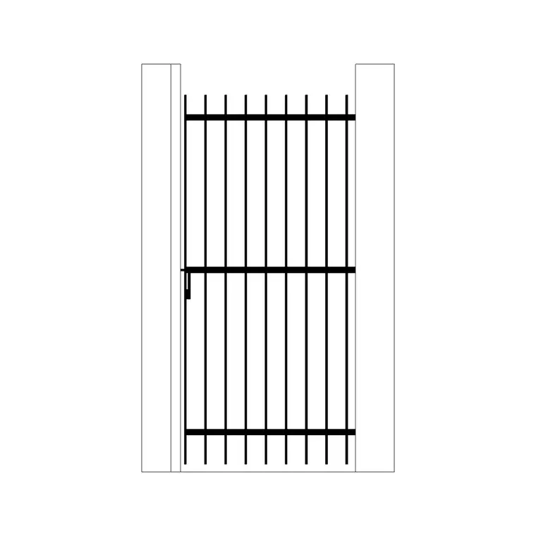
Anything on site that casts a meaningful shadow needs to be in the base drawing at roughly correct height and footprint, not just the main building. A boundary wall, a tall gate structure, or an area of paving with a different reflectance than surrounding ground, iron gate blocks and paving blocks placed at their actual site position give the study a more complete picture than a drawing that only shows the primary building massing and ignores everything else on the plot.
Existing trees and neighbouring structures matter enormously too, and while they're outside this particular block set, it's worth noting that a shading study that only accounts for the proposed building and ignores an existing tree canopy or an adjacent building's shadow is going to understate the actual overshadowing conditions a room will experience through the year.
Reflectance is a subtler factor worth mentioning too, a light coloured paving surface bounces meaningfully more light into a ground floor window than a dark asphalt driveway would, so where a shading and daylight study is being taken seriously, even the surface finish noted against the paving block in your drawing can be a genuinely relevant input for whoever runs the detailed simulation.
Setting up sections and elevations for the study
Daylight and shading assessments often need accurate sections showing window head heights, reveal depths and any external overhangs or balconies, since even a modest projecting element can meaningfully affect daylight penetration into a room below it. Build these sections from the same accurately scaled base as the plan, keeping orientation consistent so a north facing section and a south facing section aren't accidentally swapped, which is a surprisingly common and completely avoidable error when sections get drafted separately from the plan rather than derived from it.
External stairs or circulation elements near a facade, if they project far enough to cast meaningful shadow onto a window below, should be included in the section too, since it's easy to focus purely on the building envelope and miss a secondary element that's actually affecting the daylight result.
For a scheme with multiple orientations, north, south, east and west facing elevations all showing different shading conditions through the year, it's worth clearly labelling each section with its compass orientation directly on the sheet, tied back to the same north arrow reference used on the site plan, so nobody reviewing the set later has to cross reference two separate drawings just to confirm which elevation faces which direction.
Handing the drawing off for the actual analysis
Once the base is accurately built and oriented in CAD, it typically gets exported or rebuilt as a 3D model for the actual sun path and daylight factor analysis, whether that's in SketchUp for a shadow study using its built in sun position tool, or a dedicated daylight simulation package for a formal report. Keep your CAD file's units, scale and orientation clean and clearly noted before handoff, since a modeller working from your base shouldn't have to guess whether the drawing is in millimetres or metres, or whether true north matches the arrow shown.
A short note on the drawing itself, orientation reference, units, and date of latest site verification, saves the person doing the actual shading analysis from having to chase you for clarification mid study.
Common mistakes on shading study base drawings
A handful of mistakes show up repeatedly on the CAD side of shading study preparation. The first, beyond the orientation error already mentioned, is inconsistent scale between the plan and the sections used for the study, someone builds the plan at one scale from a survey and the sections from a slightly different, older set, and the two don't actually agree on window head height or reveal depth when cross checked, which throws off the daylight penetration calculation without anyone noticing until the results look odd.
The second is forgetting seasonal variation entirely and only checking a single date, since a shading condition that looks generous at the summer solstice can be a genuinely different story in December when the sun angle is much lower, and a base drawing that's accurate is wasted if the study built on it only ever gets run for one point in the year rather than across the seasons that actually matter for the assessment being requested.
I'd also flag site levels as an easy miss, a sloped site where the proposed building sits lower or higher than a neighbouring structure changes the effective shading relationship meaningfully, so make sure your base drawing carries accurate spot levels rather than assuming a flat datum across the whole plot, since that assumption alone can throw off an overshadowing assessment on anything but a genuinely level site.
Why the groundwork matters more than it looks
The catch here is that a solar shading or daylight study is only as trustworthy as its underlying base drawing, and all the sophisticated sun path modelling in the world doesn't fix an orientation that was wrong from the start. Getting the arrow, the site boundary, and the surrounding context blocks accurately placed before the analysis begins is unglamorous work, but it's genuinely the highest leverage part of the whole exercise. It's unglamorous work precisely because it rarely gets noticed when it's done correctly, only when it's wrong and the whole study has to be rerun.
Further reading
Questions
Frequently asked
Why does the north arrow matter so much for a shading study?+
Sun path calculations are entirely dependent on true compass orientation, so if the north arrow on the base drawing is even a few degrees off, every downstream shadow and daylight calculation inherits that error.
Can a 2D CAD drawing produce a shading analysis on its own?+
Not directly, a 2D drawing sets up an accurate, correctly scaled and oriented base, but the actual shadow projection and daylight factor calculations typically happen in a 3D modelling tool with a sun path engine built on top of that base.
What site elements besides the main building should be included in a shading study base?+
Boundary walls, gates, paving and any structure tall enough to cast meaningful shadow, along with existing trees and neighbouring buildings, since omitting them tends to understate real overshadowing conditions.
Free downloads from this article


Free CAD block library
Download the blocks from this article — free, no signup