Blocks for a measured survey drawing
When to use CAD blocks versus raw measured polylines on a survey drawing, and how to keep an existing conditions plan honest and accurate.
Sumana KumarUpdated 1 May 20266 min read
Survey drawings live and die on the honesty of the linework
A measured survey is the one drawing type in the whole project where the geometry has to be a faithful record of what's physically there, not an interpretation or a tidy version of it, and that puts real tension on how you use blocks, because a block by definition is a standardised, repeatable piece of geometry while a survey is fundamentally about capturing the specific and often irregular reality of one particular building. Getting that balance right, knowing when a block is an appropriate shortcut and when it's actually lying about what you measured, is the core skill of good survey drafting.
My rule of thumb after years of doing these is that anything structural or dimensionally critical gets drawn from actual survey points, while anything that's genuinely a standard catalogue item, a specific model of door hardware for instance, can reasonably be represented with a block once its position and orientation are confirmed on site.
Where blocks are a legitimate shortcut
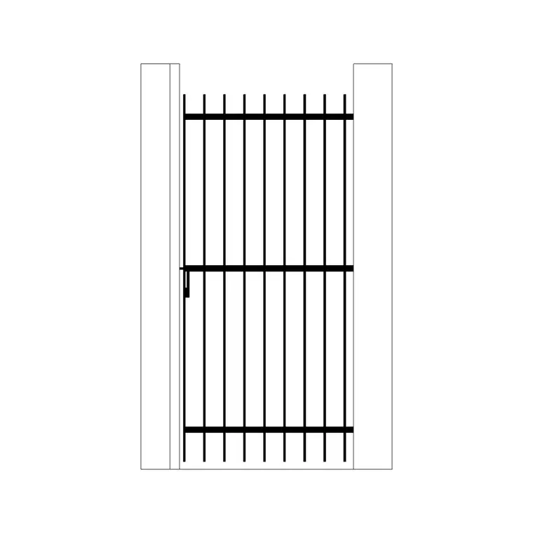
Fixtures and fittings that are genuinely standardised, like sanitary ware, or elements where the manufacturer's exact profile doesn't materially affect the drawing's purpose, are fair game for block insertion once you've confirmed position, orientation and rough size on site. A gate, for instance, if it's a stock pattern rather than bespoke, can be represented with an appropriately scaled iron gate block rather than measuring and redrawing every scroll and finial by hand, as long as the opening width and swing are verified against the actual installed unit.
The north arrow is an obvious one too, every survey needs orientation marked clearly with an arrow block, and there's no argument for hand drafting that from scratch on every single sheet when a locked, correctly rotated block does the job instantly and consistently across a whole set.
Site furniture and small fixed fittings, the kind of thing that appears repeatedly across a larger site survey, benefit from this approach most, since redrawing the same standard item by hand dozens of times across a large plot adds hours of drafting time without adding any accuracy the client actually needs from the deliverable.
Where blocks are the wrong tool
Anything with irregular or site specific geometry, an existing staircase with treads that have settled unevenly over decades, a boundary wall that's out of true, needs to be drawn from actual survey points, total station data or a laser scan point cloud, not approximated with a generic stair or wall block. Using a symmetrical circular stair block to represent an existing stair that's actually slightly out of round because the building has moved over its lifetime would misrepresent the survey, and if that drawing later gets used to design a replacement or a structural intervention, that inaccuracy becomes a real liability.
Paving and hardstanding are a judgment call, if the existing surface is a genuine regular module in good condition, a paving block representing that pattern is reasonable, but if it's patched, uneven or mixed materials, which is common on older properties, it's more honest to show the actual extent as measured polylines with a note describing the condition rather than implying a uniformity that isn't there.
The same caution applies to any element that's likely to inform a structural assessment downstream, an existing lintel over a doorway or an opening in a load bearing wall, since representing these with a generic block rather than measured geometry risks a structural engineer working from dimensions that don't actually match the building, with consequences well beyond the survey drawing itself.
Point cloud and laser scan context
On larger or more complex surveys, laser scanning and point cloud capture have become common enough that it's worth mentioning how blocks fit into that workflow. A point cloud gives you extremely accurate raw geometry, but it still needs interpretation into a usable 2D or 3D drawing, and that's where the same judgment applies, structural and irregular elements get traced faithfully from the cloud while genuinely standard fittings can still be represented with a library block once you've confirmed the cloud data matches its approximate footprint.
This hybrid approach, precise measured linework for anything unique paired with library blocks for confirmed standard items, tends to be the fastest way to turn a scan or a total station survey into a usable drawing without sacrificing the accuracy that makes a measured survey worth commissioning in the first place.
Annotating confidence levels
It's worth adopting a habit of noting, even briefly in a drawing note or separate schedule, which elements were measured directly and which were represented with a standard block based on visual confirmation rather than a full dimensional check. This sounds like extra paperwork but it protects you later if a question comes up about the accuracy of a specific element, and it gives anyone using the survey downstream, a structural engineer or a future designer, an honest sense of where the drawing is precise versus where it's a reasonable approximation.
For instance, noting 'gate represented by standard block, opening width field verified, decorative detail not individually surveyed' is a small addition that saves a lot of confusion if someone later needs to know exactly how much to trust that part of the drawing.
A worked example of the judgment call
To make this concrete, imagine surveying an older terraced property with an original iron gate at the front boundary and a stone staircase leading up to the entrance that's clearly settled unevenly over a century of use. The gate, once you've confirmed on site that it's a genuinely standard pattern with no bespoke ironwork, gets represented with a library block, position and opening width field verified against the actual installed unit, decorative scrollwork not individually redrawn since it doesn't affect anyone's future design decisions.
The staircase is the opposite case entirely, because those uneven treads are exactly the kind of information a future designer needs if they're planning to retain and work around that stair, so it gets measured tread by tread from total station points or a scan, riser heights noted individually rather than assumed uniform. Representing that stair with a clean, symmetrical block would technically save drafting time, but it would hand the next person working from your survey a drawing that quietly lies about the one thing that actually matters there. That's the whole judgment call in miniature, time saved has to be weighed against what the drawing's actual future use is going to be.
The bottom line on blocks in survey work
Blocks earn their place in a measured survey when they save time on something genuinely standard without compromising the accuracy the drawing exists to provide, and they're the wrong tool the moment they'd paper over something irregular that a future reader actually needs to know about. Keeping that distinction clear, and being honest in your annotation about which is which, is what separates a survey drawing people can rely on from one that just looks complete.
At the end of the day, the client commissioning a measured survey is paying for confidence in the drawing's accuracy above almost everything else, and every shortcut taken with a block needs to be weighed against whether it genuinely preserves that confidence or quietly erodes it.
Further reading
Questions
Frequently asked
Can I use a standard CAD block for an existing gate on a survey drawing?+
Yes, as long as it's a genuinely standard pattern and you've field verified its opening width, swing and position, though it's worth noting on the drawing that the decorative detail itself wasn't individually surveyed.
Should an existing staircase be drawn from a block or measured directly?+
Measured directly wherever possible, since older staircases often have settled or irregular going and riser dimensions that a standardised block would misrepresent, and that inaccuracy can matter later if the stair gets replaced or altered.
How does laser scanning change how blocks get used in survey work?+
A point cloud gives highly accurate raw geometry, but it still needs interpreting into usable drawing linework, and the same rule applies, irregular elements get traced from the scan while confirmed standard fittings can still be represented with a library block.
Free downloads from this article


Free CAD block library
Download the blocks from this article — free, no signup