Why a CAD block can render differently in another program
The specific technical reasons a downloaded CAD block can look fine in one CAD program and render differently once opened in another.
Sumana KumarUpdated 6 April 20265 min read
Same file, different picture, and it always has a specific cause
This is one of those situations that feels almost unsettling the first time it happens to you, you open a drawing that looked perfectly normal on your colleague's screen and something about it, a hatch, a line weight, a color, just looks subtly wrong on yours. It's easy to assume the file is corrupted, but in my experience it's almost never that dramatic. There are really only a handful of specific, well understood reasons this happens, and once you know them, diagnosing which one you're dealing with usually takes under a minute.
I find it genuinely helpful to walk through these causes in order of how often they actually turn out to be the culprit, rather than alphabetically or by technical complexity, since that ordering is what actually gets you to an answer fastest when you're staring at a drawing that just looks wrong.
Hatch patterns, the most common culprit by far
Standard hatch patterns, ANSI31, the crosshatch you see constantly on section cuts, are bundled with every DWG-compatible program and render identically everywhere. Custom hatch patterns, defined in a PAT file someone built for a specific texture or material representation, only render correctly on a machine that has that exact PAT file installed. When it's missing, the software doesn't just leave the area blank, it typically substitutes a solid fill or falls back to the nearest standard pattern it can find, which can turn a subtle material texture into a solid black block or an entirely different crosshatch density without any warning.
This is the one I'd genuinely check first every time, since in my experience it accounts for more of these reports than fonts, linetypes, color and plot styles combined, largely because custom hatch patterns are so commonly used for material call-outs on architectural and interior drawings specifically.
Fonts change more than just the letters
A missing font gets substituted automatically, but the substitute font almost never has identical character widths to the original, so text that fit neatly inside a label box can suddenly overflow it, or a dimension string can shift enough to overlap the geometry it's meant to be labeling. This is purely a cosmetic issue in the sense that the underlying data hasn't changed, but visually it can make a block look broken even though every coordinate inside it is exactly where it was drawn.
It's worth remembering that this specific issue is purely cosmetic and completely reversible, installing the correct font and reopening the drawing fixes it instantly, which is reassuring the first time you encounter it and start worrying the file itself has been damaged in some way.
Linetype scale interprets the same number differently depending on context
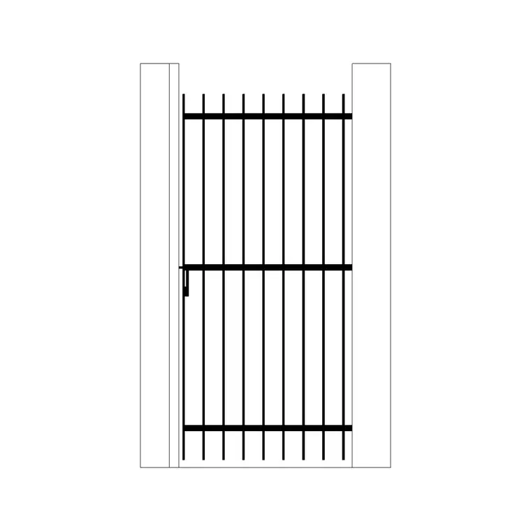
The LTSCALE and PSLTSCALE system variables control how long the dashes and gaps in a linetype appear, and these are set at the drawing level rather than baked into the block itself. A gate outline drawn with a dashed linetype can look correctly dashed in the original drawing and then appear either solid, because the drawing it's inserted into has a much larger overall scale, or oddly stretched, because the scale is much smaller, purely because of how that specific drawing's linetype scale settings interact with the block's geometry size. It's a scale interaction issue more than a software compatibility issue in the strict sense, but it gets blamed on the receiving program constantly because that's where you actually notice it.
The tell here is usually consistency, if every dashed line in the drawing looks off by roughly the same proportion rather than just the one block, that points strongly at a drawing-level scale setting rather than anything specific to the block or the software that opened it.
Color: ACI index versus true color
Older-style AutoCAD Color Index values, the numbered palette from 1 to 255, and newer true color RGB values are both fully supported across essentially every current DWG-compatible program, so this is less of an issue than it used to be. Where it still occasionally surfaces is on older or more limited software that maps true colors down to the nearest ACI equivalent for compatibility reasons, which can shift a precise custom RGB shade to a slightly different standard color. It's a minor visual difference in most cases, but it's worth knowing about if a block's color looks close but not quite right after opening in unfamiliar software.
In practice this is the least likely of the five to actually be your problem on modern software, since true color support is now close to universal across the DWG-compatible ecosystem, but it's worth ruling out quickly rather than assuming since it takes only a glance at the Properties palette to confirm.
Plot styles are a separate layer from what you see on screen
CTB and STB files control how a layer's color translates into a printed lineweight, and this is a step removed from the drawing's actual geometry and colors, meaning it can look identical on screen in two different programs but plot completely differently if one machine has the correct plot style table and the other is falling back to a default. This one specifically only shows up at print or PDF export time, which makes it the sneakiest of the group since everything can look perfectly fine right up until you actually plot the drawing.
I'd genuinely recommend doing one test plot early on any drawing headed to unfamiliar software rather than waiting until the deliverable is due, purely because this specific issue is invisible until that exact moment and there's no way to catch it just by looking at the screen.
A short list to check first, in order
When something looks off after opening a block in unfamiliar software, check custom hatch patterns first, since they're the single most common cause, then fonts, then linetype scale, then color mode, and finally plot styles if the issue only shows up in print or PDF. Working through them in that order, roughly matching how often each one is actually the culprit, gets you to the answer fast rather than guessing randomly at what changed.
Once you've been through this list a few times it stops feeling like troubleshooting and starts feeling like a quick checklist, which is really the goal, turning what looks like a mysterious rendering bug into a five item list you can work through calmly instead of a source of genuine stress mid-deadline.
Further reading
Questions
Frequently asked
Why does a hatch pattern on a block look wrong in a different CAD program?+
This is almost always a missing custom PAT file. Standard hatch patterns render identically everywhere, but a custom pattern only displays correctly on a machine that has that specific PAT file installed, otherwise it substitutes a solid fill or the nearest standard pattern.
Can the same block plot differently even if it looks identical on screen?+
Yes. This points to a plot style difference, since CTB and STB files control how layer colors translate to printed lineweight, and that mapping can differ between machines even when the on-screen appearance matches exactly.
Is a rendering difference between CAD programs a sign of file corruption?+
Almost never. It's typically one of a handful of well understood causes, missing fonts, missing custom hatch patterns, linetype scale, color mapping or plot styles, none of which indicate anything is actually broken in the underlying geometry.
Free downloads from this article
Free CAD block library
Download the blocks from this article — free, no signup