Vimar-Style Socket and Switch CAD Blocks (DWG)
Free DWG blocks styled after Vimar's modular switch and socket plates, for electrical layout plans and interior elevations, no signup needed.
Saumyajit MaityUpdated 5 July 202611 min read
Why switch and socket blocks matter more than their size suggests
A switch plate is a small thing to spend a whole blog post on, I know, but I've watched enough electrical layout reviews get held up by exactly this kind of small detail to take it seriously, because a socket or switch block that looks generic or wrong on an interior elevation is the kind of thing a design-conscious client notices immediately even if they can't articulate why the drawing feels off. The plate is one of the few pieces of infrastructure a client actually touches every day, so it earns more visual attention in a CAD block than its physical size would suggest.
For anyone drafting interior elevations, especially the kind that get presented to a client rather than just issued to an electrician, having a socket and switch block that actually looks like a considered product rather than a generic rectangle changes how finished the drawing reads. That's really the whole case for a dedicated modular-style switch and socket block set, and it's what this post walks through, alongside the honest limits of what "styled after" a known product line actually means.
What "Vimar-style" means on our library (and what it doesn't)
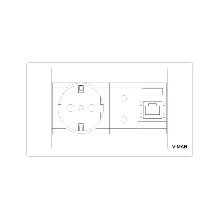
Here's the plain framing, upfront. Our library has 19 real, downloadable socket and switch blocks whose design references the clean, modular rocker-and-plate aesthetic that Vimar's own switch ranges are known for, things like flush modular buttons and compact combined socket-plus-data-point plates. These are blocks styled in that visual language, not an official Vimar product download and not a partnership with the brand. If a project has specified genuine Vimar hardware, you'd still be pulling the manufacturer's own CAD resources or spec sheet for the construction-accurate version.
What our blocks are good for is exactly what a generic library block is good for anywhere else on a drawing, representing the aesthetic and footprint of that modular plate style during design development and on interior elevations, without needing to chase down a manufacturer's CAD portal for every switch position on every wall. Once a project locks a specific hardware spec, the electrical contractor and the manufacturer's own submittal drawings take over as the source of truth, same as with any branded fixture.
I'd rather say that plainly here than let a reader assume more than the blocks actually are, because a false download promise on something as small as a switch plate is still a false promise.
The modular plate look, and why it's become a default aesthetic
The modular rocker-and-plate look has become close to a default expectation in mid to high end interior work over the last decade or so, replacing the older toggle-switch aesthetic almost everywhere except budget or older-stock projects. It's a flush plate, usually square-ish rockers or square button modules set into a shared frame, sometimes combined with a data or TV point on the same plate so a wall doesn't end up peppered with separate faceplates for every service.
That combined-plate approach is actually one of the more useful things to model correctly in a block, because it changes wall layout planning. A single combined plate housing a power socket, a TV coax point and a network point takes one wall opening and one legend entry, versus three separate faceplates each needing their own position and their own line in a schedule. If a project genuinely wants that consolidated look, drafting it with a combined block from the start avoids relayering three separate symbols on top of each other later.
Whichever specific plate style a project ends up specifying, drafting the intent early with a modular-style block gets the conversation with a client or an electrical designer started on the right visual footing, which is worth more in early design meetings than it sounds.
Practical sizes and mounting heights worth knowing
On the sizing side, there's genuine published convention worth knowing even though the exact numbers always defer to local electrical code and manufacturer spec. Modular switch and socket plates in this style are commonly built around a roughly 80 to 90mm square single-gang module, ganging up to double or triple width for combined plates, which is why you'll see single, double and multi-button variants in a block set built to represent this aesthetic.
Mounting height is the other number that comes up constantly in interior drafting, and the honest answer is that it varies by region and by project brief rather than having one universal figure, though a switch height in the rough 900 to 1100mm range above finished floor and a socket height somewhere from just above skirting up to roughly 300 to 450mm are common defaults in a lot of residential interior work, with accessibility-focused projects often specifying both switches and sockets at more uniform, reachable heights across that range. Always check the project's own electrical drawings or local code requirement rather than treating any of this as a fixed rule, since it genuinely isn't one everywhere.
For drafting purposes, what actually matters most is getting the block's footprint right at true scale so wall elevation clearances, next to door swings, next to furniture, next to worktops, can be checked visually before construction, which is exactly the kind of check a good elevation block earns its place by enabling.
Kitchen and worktop scenarios are worth calling out specifically since they are the most common place a socket height genuinely gets scrutinized during a fit-out review, a socket positioned above a worktop needs to clear the worktop surface itself, commonly by a modest margin somewhere in the range of 100 to 150mm, while also sitting low enough to actually be reached comfortably and to clear any upper cabinetry or a backsplash feature above it, which on a tiled splashback specifically often means coordinating the exact socket height against the tile course lines so the plate lands cleanly within a single row rather than straddling an awkward tile cut. This is exactly the kind of coordination that benefits from drafting the switch and socket block directly onto the kitchen elevation early, rather than leaving socket position as a note to be resolved on site, since resolving a tile-course clash on a drawing costs nothing and resolving the same clash after tiling is finished costs a redo.
Where these blocks actually belong on a drawing set
These blocks belong on interior elevations and on electrical layout plans, and less so on a pure architectural floor plan, where socket and switch positions are more often shown as a simple symbol with a code reference back to the electrical drawings rather than a fully rendered plate block. Where the modular plate block genuinely shines is on presentation elevations, the kind of client-facing wall elevation that shows finishes, fixtures and switch plates together so a client can actually picture the finished wall.
It's also useful groundwork for a combined FF&E and fixtures legend on a fit-out sheet, sitting alongside furniture and accessory entries, since switch and socket plates are genuinely part of the fixtures tier of an FF&E schedule even though they're easy to forget when a legend gets built furniture-first.
On a construction issue set proper, expect the electrical layout to still carry the authoritative symbol and circuiting information, with the elevation block serving the visual, coordination and client-communication role alongside it rather than replacing it.
Fitting switch and socket blocks into a broader electrical symbol set
A socket or switch block never really stands alone on a drawing, it's one entry in a broader electrical symbol set that usually also includes light points, junction boxes, distribution board references and sometimes low-voltage or smart-home control points, and a fixtures legend that only shows the modular plate style without noting how it relates to that broader set leaves out useful context for whoever is reading the drawing on site. It's common practice, and worth adopting even on a small residential set, to note against each socket and switch symbol which circuit or zone it belongs to, tying the visual block back to the actual electrical design rather than treating it as pure decoration.
Wet areas add another layer worth knowing about generally, even though it isn't something a block library itself resolves. Bathrooms, kitchens near sinks, and any outdoor socket location typically call for a different, protection-rated fixture under most electrical codes, and that's a real constraint on final hardware selection that a generic styled plate block can represent visually on an elevation but can't specify technically. If a project has wet-area sockets, the electrical designer's own specification, not the CAD block, is what determines the actual protection rating required, and that's worth flagging to a client early rather than after a wet-area plate gets ordered to match a dry-area aesthetic.
Keeping this broader context in mind is really what separates a socket and switch block used well from one used as an afterthought, it's a small piece of a bigger coordinated electrical picture, and drafting it that way, referencing circuits, respecting wet-area exceptions, keeping mounting heights consistent, is what makes the fixtures legend actually useful to the people building from it.
Smart home and low voltage control points are worth a specific mention here too, since a growing share of interior fit-out projects now specify a touch panel or a smart switch alongside, or instead of, a traditional rocker plate, and that device typically carries its own distinct footprint and mounting depth that a generic modular-style block will not automatically represent correctly. Where a project scope includes smart control, it is worth confirming with the electrical designer or the smart home integrator whether the wall box depth and plate footprint actually match the modular aesthetic block being used for the rest of the plan, since a mismatch there is a coordination detail worth catching in design development rather than after wall boxes have already been roughed in.
Common mistakes with electrical symbol blocks
The most common mistake is treating a styled socket block as if it were an official manufacturer download, then specifying it in a submittal as if it guarantees a specific product match. It doesn't, and being clear about that with a client or a contractor early avoids an awkward correction later when actual hardware gets ordered and it doesn't match the exact plate style shown on a presentation drawing.
A second, more mundane mistake is inconsistent plate orientation and mounting height across a set of elevations, switches drawn at one height on one wall and a visibly different height on another wall of the same room with no design reason for the difference, which reads as a drafting error even when it might have been intentional.
- Mixing generic rectangle symbols and detailed modular blocks on the same elevation - Forgetting to include combined data or TV points where the project scope calls for them - Not cross-referencing elevation switch positions back to the electrical layout plan - Treating a styled block as brand-accurate in a client submittal document
Naming and organizing these blocks in your own project library
However many of these plates end up on a project, keeping them named and organized deliberately in your own working library pays off the first time a mid-set revision, adding a socket, moving a switch, relocating a combined data point, needs to happen fast. Prefix each variant consistently in your block naming, something like SW-VIMAR-1G for a single-gang switch or SOC-VIMAR-2G for a two-gang socket, so a search inside the drawing turns up every plate variant together rather than scattered under whatever generic name the block happened to import with.
It's also worth purging unused variants before issuing a set, since a drawing that's accumulated six socket block definitions over several revisions but only actually uses two of them on the current plan carries dead weight that slows file loading and confuses anyone auditing the block table later. A five minute purge pass before issue, alongside the same check on any other block family in the drawing, keeps the file lean and keeps the block table an honest reflection of what's actually on the sheet.
None of this changes how the blocks look or function, it's just the housekeeping that turns a one-off download into a reusable part of your own standard library, which is really the point of building a legend and a symbol set worth reusing project after project rather than resourcing switches and sockets from scratch every time.
What's really in the Vimar-style set on cadblockdwg.com
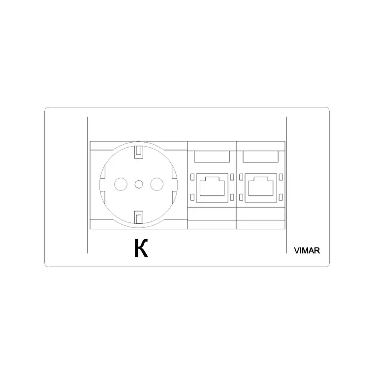
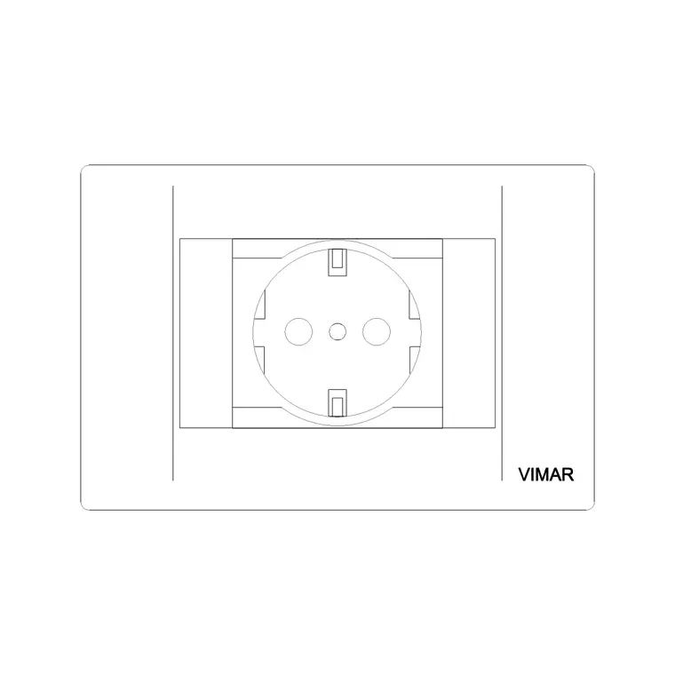
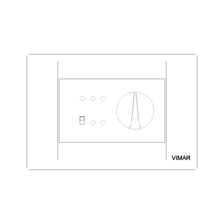
Our Vimar-style set holds 19 real, downloadable blocks in the office category, single and multi-button socket plates, combined TV and LAN point plates, and separate LAN and TV cable socket variants, all free to download and free for commercial use with no account needed. That's enough range to cover most single-gang through multi-gang combined plate scenarios you'd want to show on an interior elevation or fixtures legend.
What it won't do is stand in for an actual manufacturer submittal once hardware is specified, and it isn't an official Vimar resource, just blocks drawn in that visual language for design development and presentation use. Used that way, honestly labeled, it's a genuinely useful shortcut for anyone drafting interior elevations who doesn't want to redraw a modular switch plate from scratch every time one shows up on a wall.
Further reading
Questions
Frequently asked
Are these official Vimar CAD blocks?+
No. They're blocks styled after the clean modular rocker-and-plate aesthetic that Vimar's ranges are known for, not an official brand download or a partnership. If a project has specified genuine Vimar hardware, use the manufacturer's own CAD resources for the construction-accurate version.
What mounting height should I draft switches and sockets at?+
It genuinely varies by region and project brief, so always check local code and the project's electrical drawings first. A switch height roughly in the 900 to 1100mm range above finished floor and a socket height from just above skirting up to around 300 to 450mm are common defaults in a lot of residential work, but treat those as a starting point, not a rule.
Can I use these blocks on a construction issue set, or only for presentation?+
They work well on interior elevations and fixtures legends for both design development and client presentation. For the construction electrical layout itself, the electrical plan's own symbol and circuiting still carries the authoritative information, with the elevation block supporting the coordination and visual read alongside it.
How many socket and switch variants are actually in the set?+
19 real products, covering single and multi-button plates plus combined data and TV point variants and separate LAN and TV cable socket blocks, all downloadable as DWG with no account required.
Free downloads from this article
DWGElectric Socket Vimar 1
 DWG
DWGElectric Socket Vimar 2
 DWG
DWGElectric Socket Vimar 3
 DWG
DWGElectric Socket Vimar 4
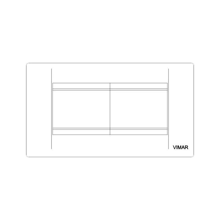 DWG
DWGElectric Socket Vimar 5
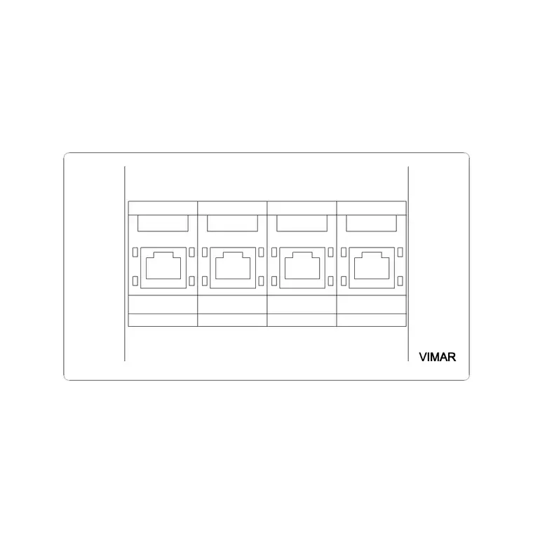 DWG
DWGLan Socket Vimar
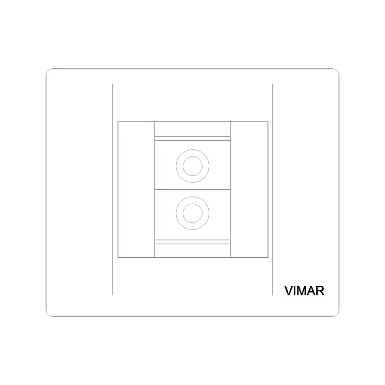 DWG
DWGTV Cable Socket Vimar
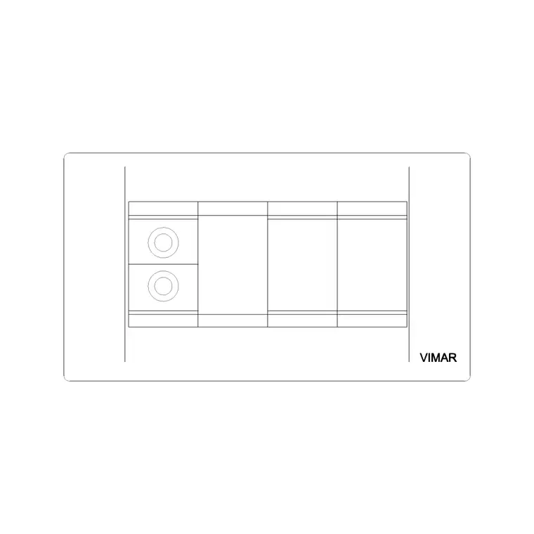 DWG
DWGElectric Socket Vimar Button With TV Point
Free CAD block library
Download the blocks from this article — free, no signup