Using free DWG blocks as a linked underlay in Revit
How to bring free DWG blocks into Revit as a linked CAD underlay, prep them properly, and decide what stays reference versus what gets modeled.
Saumyajit MaityUpdated 26 June 20266 min read
Why teams still link DWG instead of modeling everything from scratch
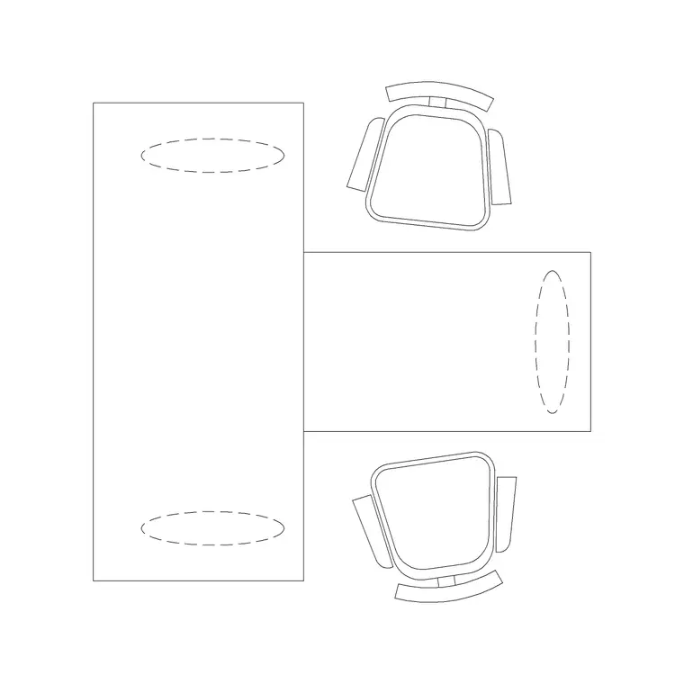
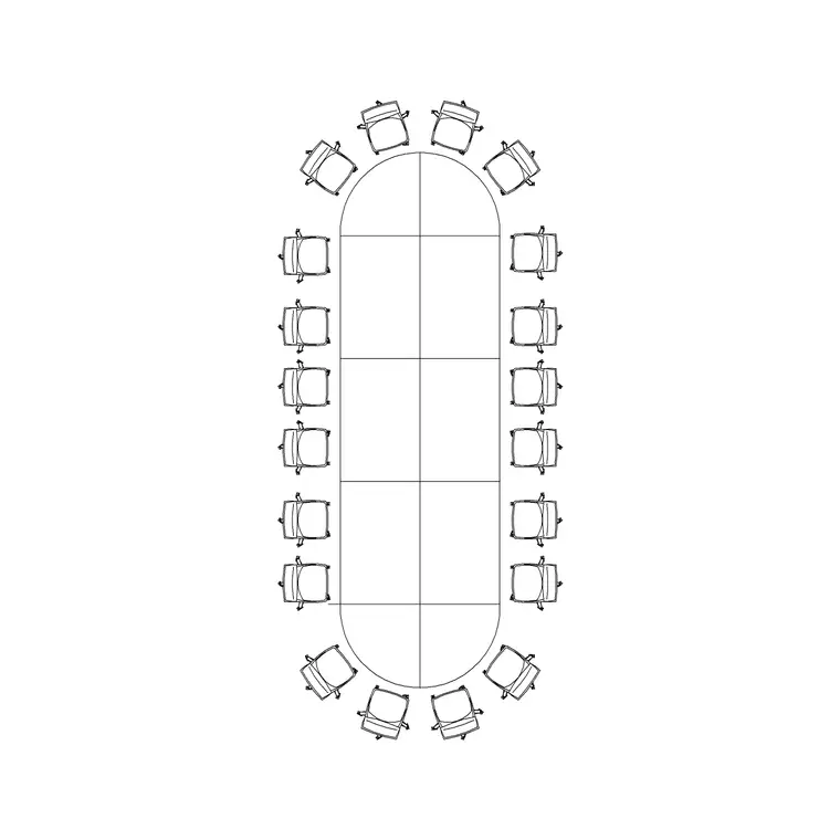
I've sat in enough coordination meetings to know the pure BIM fantasy, where every wall, door and fixture starts life as a native Revit family, isn't how most working offices actually operate day to day. A huge share of real project geometry still arrives as, or gets drafted as, plain DWG, and the fastest way to get that content in front of a model without redrawing it by hand is to link it in as a CAD underlay. Free block libraries do a lot of the heavy lifting here, because a well drawn gate, a north arrow, a two seater workstation or a twenty seater conference table gives you accurate plan view geometry you can trace, measure against, or just leave sitting under the model as reference while the team figures out what actually deserves to become a proper Revit family.
The honest reason this matters is speed, and money follows speed on most fee structures. Nobody wants to build a parametric family for a one off site element that shows up twice in the entire project, right, so linking a DWG block in as an underlay and tracing what you need from it is very often the smarter call, not a shortcut you feel bad about. I still keep a folder of downloaded blocks, doors, windows, site furniture, sitting ready specifically for this purpose, because reaching for something already drawn at real scale beats starting a family from a blank template every single time.
Getting the block ready before it ever touches Revit
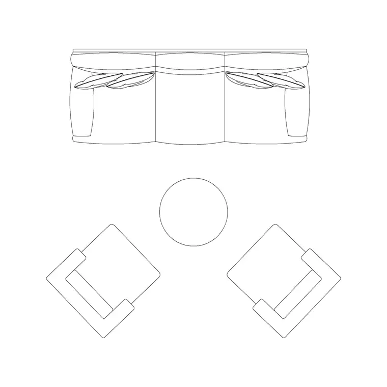
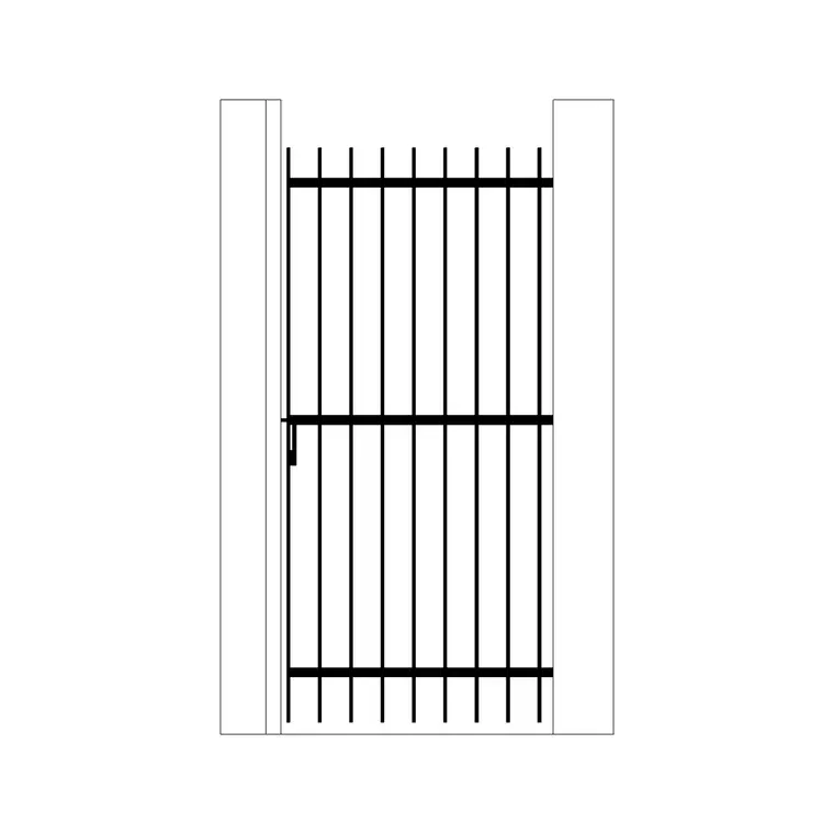
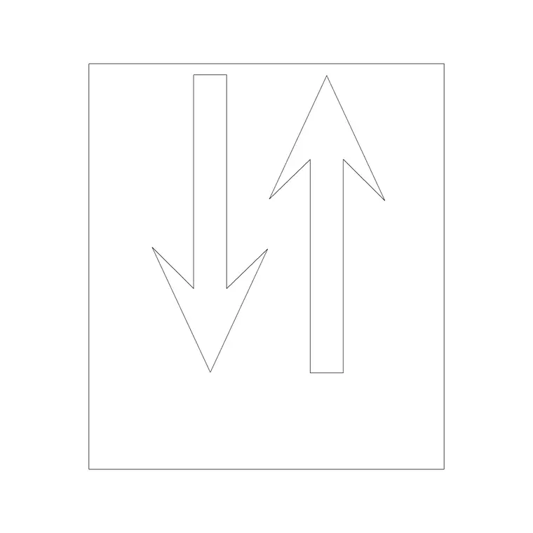
The prep work happens in AutoCAD, not in Revit, and this is the step people skip. Open the downloaded block, an iron gate block or an arrow symbol from a building symbols set for instance, and check three things before you save it off for linking, that the geometry is drawn at real world scale with INSUNITS set correctly, that it sits on a sensibly named layer rather than layer zero buried inside a nested block, and that there's no stray geometry sitting miles off in model space that will blow out your bounding box the moment Revit tries to link it in.
Purge the file, audit it, and if you only need one or two blocks out of a larger DWG, consider wblocking just those out into their own smaller file rather than linking the whole source drawing. A clean, small, purpose built DWG links faster and is far easier for the next person to understand than a link that drags in an entire library's worth of geometry nobody asked for.
This is also the point to decide DWG or DXF. If your consultant or the person receiving the file is on an older CAD platform or a non Autodesk viewer, exporting the source block to DXF before handing it over avoids version compatibility headaches, since that's the entire reason the DXF file format exists in the first place. Either way, download from a category page like doors or building symbols rather than a random forum thread, so you actually know the block's scale and layer history instead of inheriting someone else's undocumented cleanup job.
Linking it in and choosing positioning correctly
In Revit, Insert, Link CAD is the tool, and the positioning option you pick at that dialog matters more than people give it credit for. Auto, Center to Center is fine for a quick placeholder check, but for anything that needs to land on a real coordinate, use Auto, By Shared Coordinates if the DWG was set up against the same base point as your project, or Manual, Origin to Origin if you trust the DWG's own zero comma zero point. Getting this wrong is the single most common reason a linked underlay shows up rotated ninety degrees or offset by a full building width from where everyone expects it to sit.
Set the link's layer visibility per view rather than globally, so a reference underlay full of furniture blocks doesn't clutter a structural view three sheets over. And always link, don't import, unless you have a specific one off reason not to. A link updates when the source DWG changes, which is basically the whole point of using this as a live coordination tool instead of a one time trace you'll have to redo by hand later.
Deciding what stays 2D and what gets modeled
Once the underlay is in, the real judgment call starts. Site furniture, one off symbols, an arrow or grid marker, gate and fence details on a landscape sheet, these are often fine staying as linked 2D content forever, because modeling them natively buys you nothing except extra file weight and another family to maintain. Repeated elements that need to schedule, clash check, or appear consistently across dozens of sheets, an office workstation layout that recurs on every floor or a conference table that shows up in six different meeting rooms, are worth the time to rebuild as a native family, because that's where BIM's real value, quantities, clash detection, live scheduling, actually shows up.
At the end of the day the underlay isn't a permanent home for content, it's a workspace where you decide what's worth promoting into the model and what's genuinely fine staying flat. I usually make that call within the first coordination cycle, not months in, because leaving it unresolved just means the same conversation happens again later under more time pressure.
Keeping the link healthy over the life of the project
Linked CAD files are notorious for quietly bloating a Revit model if nobody manages them, so put a light process around it from day one. Keep source DWGs in one shared, version controlled folder rather than scattered across desktops, reload links after every coordination cycle rather than letting them drift out of sync, and periodically run through Manage Links to bin anything nobody is actually using anymore. I've opened models with a dozen stale CAD links nobody remembered linking in, and every single one of them was silently adding to open and sync times for no benefit at all.
If a link is only ever used for measurement reference, mark it not for export and set its display to halftone so it visually recedes behind the real model content, which keeps the team from accidentally treating reference geometry as if it were authoritative. Name the link itself sensibly too, not just the source file, because Revit's Manage Links dialog gets unreadable fast once a project has a dozen entries all called by their default filename.
Common problems and how to catch them early
Three issues show up again and again with linked DWG underlays, and all three are catchable in under a minute if you know to look. A block that comes in roughly twelve times too big or too small almost always means an inches versus millimeters mismatch, check INSUNITS in the source file rather than fighting it with a manual scale factor in the link dialog. A block that appears rotated is nearly always a base point mismatch, fix the UCS in AutoCAD before you export rather than trying to nudge it straight inside Revit. And a link that seems to be missing half its layers is usually a VISRETAIN or frozen layer state carried over from the source file, so open the DWG directly and check layer states before assuming the block itself is broken.
None of this is exotic troubleshooting, it's just the same handful of checks every time, and once you've run through them a few times on real projects they stop being a mystery and start being a thirty second habit before you ever open the Link CAD dialog.
Further reading
Questions
Frequently asked
Will a linked DWG block scale correctly in Revit automatically?+
Only if its source units and INSUNITS setting are correct before linking. Revit reads the DWG's internal units, so a block drawn in millimeters that was accidentally saved with unitless or inch settings will come in at the wrong size, always check with a quick dimension right after linking.
Should I explode a linked DWG block to edit it inside Revit?+
Generally no. Exploding breaks the live link relationship, so any future update to the source DWG stops flowing through to your model. If you need to edit the geometry, do it back in AutoCAD on the source file and reload the link instead.
Is linking CAD considered a legitimate BIM workflow or just a workaround?+
It's a genuinely common hybrid workflow used across most practices that still receive 2D deliverables from consultants, clients or older projects. The key is being deliberate about what stays linked reference and what eventually gets promoted to native BIM content.
Free downloads from this article
Free CAD block library
Download the blocks from this article — free, no signup