Street light CAD blocks for a site and landscape plan
How to size, space and draft street light CAD blocks on a site or landscape plan, from pole height to spacing along a path.
Sumana KumarUpdated 1 April 20265 min read
Lighting the site, not just the building
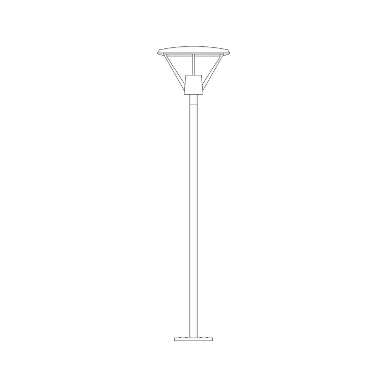
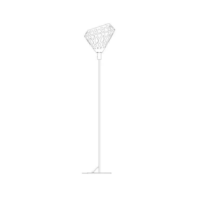
Most of the lighting conversation on a project happens inside the building, but the moment you zoom out to the site plan or the landscape drawing, street lights and pole mounted fixtures become one of the few elements that actually shape how the whole exterior reads, both for a planning submission and for the finished render. The Street Light Elevation 1 block on cadblockdwg.com gives you a pole mounted fixture drawn in elevation, which is the view you need for showing height and proportion against a boundary wall, a driveway, or a row of trees along a landscape architecture scheme.
Pole height ranges you will actually see specified
Street and site lighting poles vary a lot depending on what they are lighting. Pedestrian paths and residential drives are commonly lit with poles somewhere in the 3 to 5 metre range, low enough to feel domestic and not overpower a garden or courtyard. Arterial roads and larger parking areas typically call for taller poles, often 6 to 9 metres or more, because the fixture needs to throw light over a wider area from a single point. Before you commit a pole height on a drawing, check it against your project's actual lighting design or local authority standard, since site and street lighting height is frequently a planning condition rather than a free choice.
Bollard style lighting, shorter fixtures typically under a metre tall used along garden paths or low level courtyard routes, is a related but separate category from the pole mounted street light block covered here, so if a section of your landscape plan calls for that lower, more intimate lighting rather than a full height pole, note it as a distinct fixture type on your lighting schedule rather than just scaling this block down, since a scaled down street light rarely reads convincingly as a purpose built bollard.
Spacing is the part people forget to draft
A single street light block dropped in isolation on a site plan does not tell the reviewer much, what actually communicates the lighting strategy is the spacing between poles along a route, and a loose rule of thumb used in a lot of lighting design is spacing somewhere around three to four times the pole height for even, overlapping coverage along a residential path, though this varies enormously with fixture output and local lux requirements, so treat it as a starting point for laying out the drawing rather than a final spec. What I usually do is array the block along the site plan's driveway or path centreline at a consistent interval, then check the run against the landscape plan to make sure no pole lands in the middle of a planting bed or a driveway crossing.
Elevation block, plan block, and why you need both
This particular block is drawn in elevation, which is exactly what you want for a boundary elevation, a streetscape drawing, or a rendered view showing the fixture's height relative to a fence line or a hedge. For the site plan itself, where you are looking straight down, you will want a simple plan view symbol, a small circle or a pole mark at each pole location, rather than the elevation block, since inserting an elevation view fixture into a top down plan reads as an error to anyone reviewing the drawing. Keep the two views on separate sheets doing separate jobs, elevation for showing height and character, plan for showing position and spacing.
Where it earns its place beyond the obvious driveway
Beyond the standard driveway or street application, this block is also useful along a car park perimeter, a public path through a landscaped courtyard, or as a scale reference in a boundary elevation where a client wants to see how the fixture compares to a wall or planting height, a comparison that is much easier to sell in elevation than in plan. It pairs naturally with a landscape drawing built out of tree and planting blocks along the same route, giving the whole drawing a sense of a finished, lit exterior rather than just a bare paved area.
Getting it into the drawing correctly
Download as DWG and insert with INSERT so the fixture stays as a single named block you can array or copy consistently along a route, rather than a stack of loose lines. Check the block's native scale against your drawing setup, and if your site plan is at a small scale, say 1:200 or 1:500, consider whether the elevation block is even legible at that scale or whether a simplified plan symbol communicates pole position more clearly, reserving the full elevation block for larger scale detail sheets or standalone streetscape elevations.
If the design team is split across different software for the landscape plan versus the site engineering, remember DXF exists precisely for this kind of handoff between different computer-aided design packages, so keep both formats on hand rather than assuming everyone downstream is running the same software you are. A pole light block that opens cleanly in your own setup can still need the DXF version to import properly into a civil engineering or GIS based tool the wider project team might be using for the underground utility coordination mentioned earlier.
Coordinating with the landscape and utility drawings
A street light pole is rarely just a lighting decision on its own, it also has a below ground component, a footing and a cable run back to a distribution point, so before you finalise pole positions on a site plan, cross check them against the landscape plan's planting layout and against any underground utility routing already shown on the civil drawings, since a pole footing landing on top of a proposed tree pit or directly over a drainage line is the kind of clash that is cheap to fix on paper and expensive to fix once concrete has been poured. I also make a habit of checking sightlines at vehicle entrances and junctions, since a pole positioned without thinking about driver sightlines can end up flagged by a reviewing authority even if the lighting design itself is sound. None of this changes how you use the block, it is still the same DWG elevation inserted and arrayed along your route, but it does change where along that route each instance actually lands, and that coordination pass is worth doing before the drawing goes out for review rather than after.
Further reading
Questions
Frequently asked
What pole height should I use for a residential driveway?+
Somewhere in the 3 to 5 metre range is common for domestic and pedestrian scale lighting, but always confirm against your project's lighting design or local planning condition before finalising it.
Can I use the elevation street light block directly on my site plan?+
Not really. The elevation block is built for showing height and profile against a wall or boundary. For a top down site plan, use a simple plan symbol at each pole position instead.
How far apart should street light blocks be spaced along a path?+
A common starting reference is roughly three to four times the pole height, but actual spacing depends on the fixture's output and any local lux requirement, so treat it as a first pass rather than a final answer.
Free downloads from this article
Free CAD block library
Download the blocks from this article — free, no signup