Reconciling block scale mismatches between 2D CAD and a 3D model
Where scale mismatches between 2D DWG blocks and a 3D BIM model actually come from, and how to track them down and fix them.
Saumyajit MaityUpdated 13 July 20265 min read
The mismatch that always seems to show up at the worst moment
Scale mismatches between a 2D block layout and a 3D model have a specific talent for surfacing at the worst possible moment, usually during a client walkthrough or a formal coordination review, when a workstation that looked perfectly fine on the 2D furniture plan suddenly appears to be the size of a small car once viewed inside the 3D model, or a conference table that seated twenty comfortably on paper barely fits eight once modeled at what turns out to be the actual correct scale.
This almost never comes from someone drawing carelessly, it comes from unit assumptions quietly disagreeing with each other across two different software environments, and once you know the handful of places that disagreement actually originates, tracking it down stops being a mystery and becomes a fairly quick checklist.
Where the disagreement actually starts
The most common source by a wide margin is a millimeters versus inches mismatch, a block drawn correctly at real world scale in millimeters that gets inserted into a drawing set to inch based units, or the reverse, producing exactly the kind of dramatic scale error people usually describe as everything came in huge or everything came in tiny. Check INSUNITS in the source block file first, always, before touching any manual scale factor, because fixing the actual unit setting is more reliable than layering a correction factor on top of a wrong assumption.
The second common source is a block that was never drawn at true scale to begin with, sometimes older or poorly sourced content gets drawn roughly to look right on screen at a specific zoom level rather than to genuine real world dimensions, and that error carries invisibly through 2D drafting where nobody's cross checking against a tape measure, but becomes obvious the instant the same content gets modeled or referenced at true scale in a 3D environment.
How the 3D model complicates the picture further
A 3D BIM platform typically carries its own internal unit system and project base point, independent from whatever units a linked or referenced DWG happens to use, and if those two systems aren't explicitly reconciled at link time, a block that measures correctly in isolation can still land at the wrong apparent scale once placed relative to the model's own geometry. This is different from a straightforward INSUNITS error, it's a coordination gap between two systems that were each internally consistent but never agreed with each other.
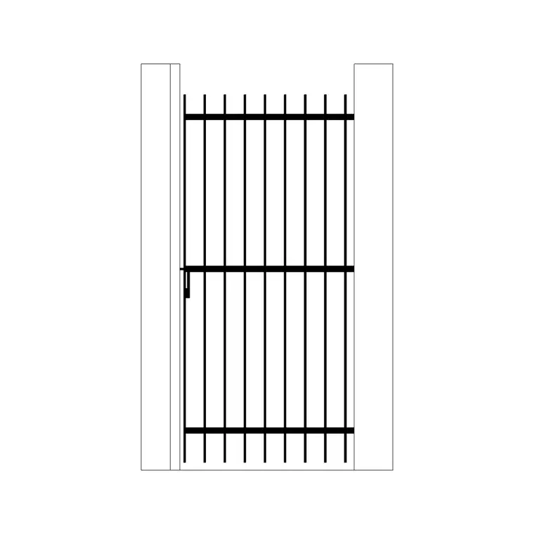
For instance, an iron gate block, correctly scaled in its own DWG file, can appear undersized relative to a modeled opening if the model's wall and opening geometry were built against a different assumed real world dimension for that gate than what the downloaded block actually represents, a mismatch that has nothing to do with unit settings and everything to do with the model and the block simply disagreeing about the object's true size.
A practical process for tracking down the actual source
Rather than guessing, work through a fixed sequence. First, check INSUNITS on the source block file and confirm it matches your project standard. Second, measure the block itself against a known dimension, a door block should measure to its stated width, a workstation to its stated footprint, using a simple distance command check rather than trusting the visual appearance at whatever zoom level you happen to be at. Third, if the block measures correctly in isolation but still looks wrong once placed, the issue is almost certainly at the link or coordination stage, not the block itself, check base points and shared coordinates next.
This sequence, unit setting, direct measurement, then coordination and base point, catches the overwhelming majority of scale mismatches in under ten minutes, which beats the alternative of a much longer, more frustrating trial and error process trying random scale factors until something looks visually right.
Preventing it from happening again on the next project
The long term fix is building a habit of verifying scale on any new block the moment it's downloaded, before it ever gets used in a real layout, rather than discovering an error mid project. A quick distance check against the product's stated real world dimensions, a conference table's stated length, a workstation's stated footprint, takes seconds and catches a scale problem while it's still cheap to fix, rather than after it's propagated through a dozen sheets and possibly into a 3D model as well.
I keep this as a genuinely automatic habit now, download a block, measure it once before first use, and it's saved me more than once from an embarrassing moment discovering a scale error in a drawing that had already gone out for review, which is a far worse time to find it than the thirty seconds it takes right after download.
A short scale verification checklist
A quick sequence worth turning into muscle memory:
- Check INSUNITS on any new block before first use - Measure the block against its stated real world dimension with a direct distance check, not visual estimation - If a block measures correctly but looks wrong once linked, check base point and coordinate alignment next, not the block itself - Re-verify scale specifically for content moving between 2D drafting and a 3D model, not just within one environment - Build scale verification into your download workflow as a standing habit, not a one time troubleshooting step
None of this is complicated once you know the sequence, the actual skill is resisting the urge to guess a correction factor and instead working through unit setting, direct measurement, then coordination, in that order, every time.
Where paper scale and model scale add another layer of confusion
A separate but related confusion shows up when a drawing's plotted scale gets mixed up with the model's actual geometric scale, and this is worth separating clearly because they're not the same thing. A floor plan plotted at 1 to 100 on an A1 sheet, sized according to the ISO 216 paper series most offices already use for their sheet sets, is still drawn at full real world scale in model space, the 1 to 100 relationship only applies at the moment of plotting or setting up a viewport, it has nothing to do with whether the block itself was inserted at the correct real world size.
I've seen this cause confusion specifically when someone assumes a block looks wrong because of the sheet's plot scale, when the actual problem is a genuine model space scale error unrelated to plotting at all, and chasing the wrong cause wastes real time. The fix is separating the two checks explicitly, confirm the block's real world model space dimensions first with a direct measurement, completely independent of whatever scale the sheet plots at, and only then look at viewport scale and sheet setup if the model space geometry itself checks out correctly.
Further reading
Questions
Frequently asked
My block came in about twelve times too small, what's the most likely cause?+
A unit mismatch between inches and millimeters is by far the most common cause of a dramatic scale error like this, check INSUNITS in the source block file before trying a manual scale correction.
How do I check if a downloaded block is actually true to real world scale?+
Use a direct distance measurement against the block's stated dimension from the product listing, rather than judging by eye at whatever zoom level the drawing happens to be at.
Can a block be correctly scaled in AutoCAD but still look wrong once linked into a BIM model?+
Yes, if the block measures correctly on its own but the coordination or base point between the DWG and the model doesn't align, the object can still appear at the wrong apparent scale once placed relative to the rest of the model.
Free downloads from this article
Free CAD block library
Download the blocks from this article — free, no signup