Blocks for an accessible-route verification drawing
The symbols and clearance checks you need to verify an accessible route on a floor plan, from entry gate to interior circulation.
Saumyajit MaityUpdated 14 June 20266 min read
Verification drawings ask a narrower question than a full plan
An accessible route verification drawing isn't trying to show everything in a building, it's trying to answer one focused question, can a wheelchair user get from the accessible entry point to every required destination, restrooms, primary function spaces, exits, without hitting a pinch point that's narrower than code allows. I draw these as a stripped down overlay on top of the base floor plan, route line, clearance zones, and the handful of symbols that actually carry meaning for an accessibility reviewer, everything else gets dimmed or turned off so the route itself is the thing your eye follows first.
The core symbol: marking the accessible route itself
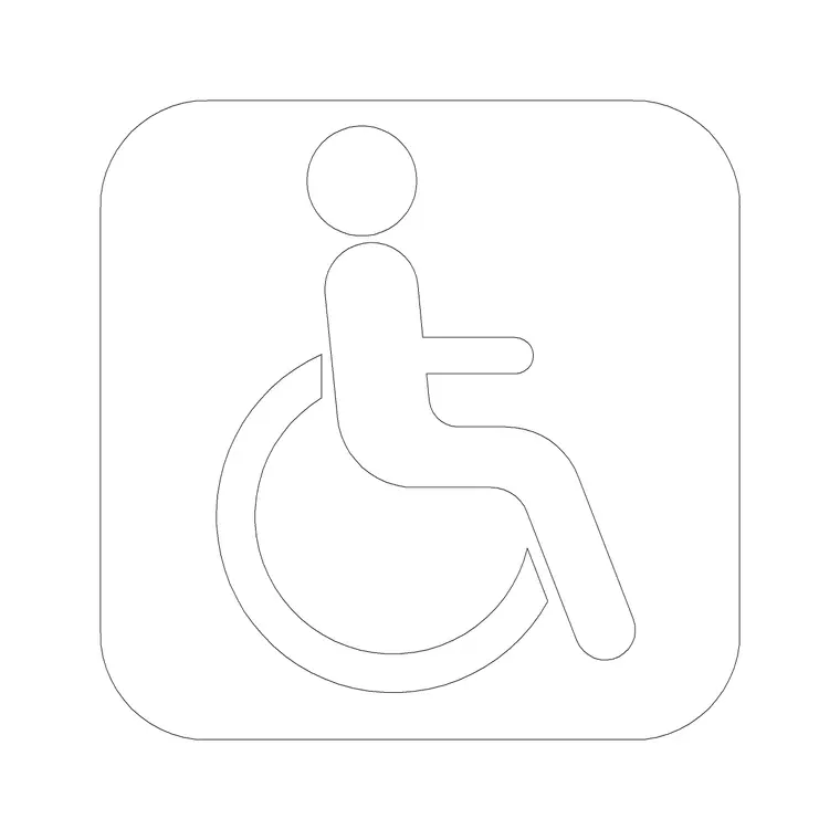
A wheelchair accessible symbol block is the anchor of this whole drawing type, used at the start of the route near the accessible entrance, again at any accessible parking or drop off point, and at destination points like an accessible restroom stall. Per Universal design and Accessibility principles that most building codes reference in some form, an accessible route generally needs a continuous, unobstructed path, so I place the symbol at every decision point along that path, not just the endpoints, because a reviewer scanning the sheet should be able to trace the full route without guessing where it continues.
Keep a running count of how many times the symbol appears against how many required destinations your project actually has, restrooms, primary function spaces, exits, because a route that technically connects the entrance to one restroom but misses a second required destination is an incomplete verification even if every individual symbol on the sheet is placed correctly. I treat that count the same way I'd treat a schedule cross check on an FF&E drawing, a simple tally that catches an omission before a reviewer does.
Doors and gates along the route
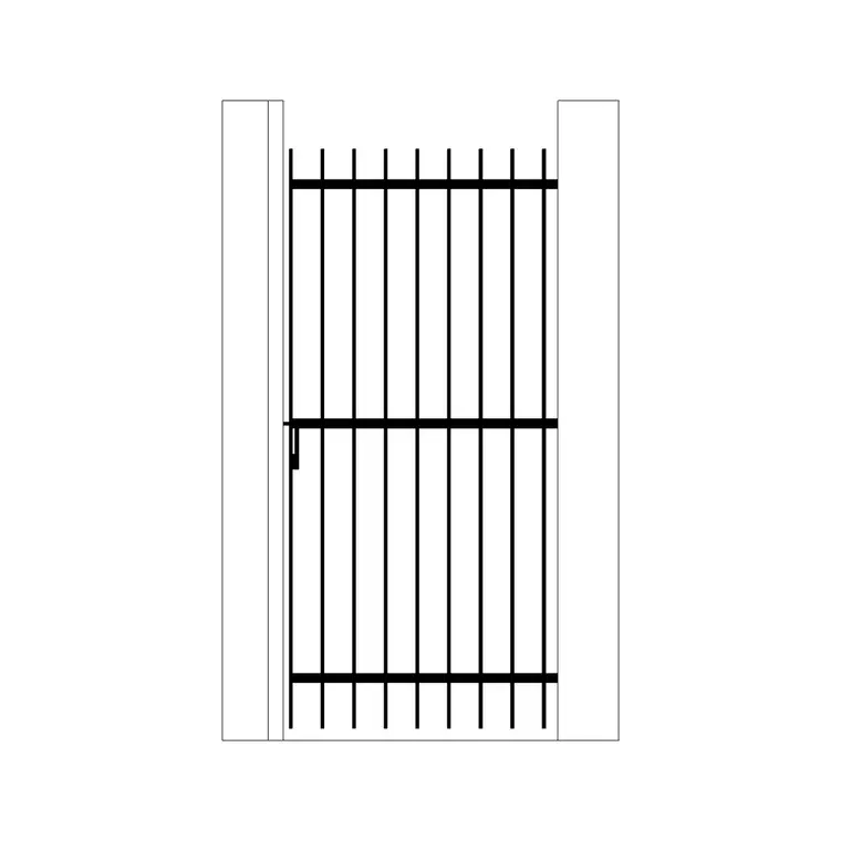
Every door and gate on the verified route needs its clear opening width checked, and this is where a gate block like an iron gate becomes relevant if the route passes through an exterior threshold, a garden entry, or a site boundary gate rather than only interior doors. Clear width requirements vary by code and jurisdiction so I won't quote a single number as gospel, but accessible door openings are commonly specified somewhere in the 800 to 900 mm clear width range in many codes, so check your local requirement and annotate the actual clear width, not the nominal door size, next to each opening on the route.
The maneuvering clearance on the latch side of a door matters just as much as the clear opening width, and it's the detail I see missed most often on a route drawing that otherwise looks complete, because a door can have a generous clear width and still fail the route if there isn't enough level floor space beside the handle for a wheelchair user to pull it open without backing into a wall. I mark this clearance as its own dimension string on the drawing, separate from the door width callout, specifically because a reviewer scanning quickly tends to check the width number and move on, and the maneuvering space is the number that actually gets missed on site more often than the width itself. Threshold hardware matters here too, a door closer set too aggressively can make an otherwise compliant opening functionally inaccessible, so if the door has a closer specified, note the required opening force on the drawing rather than leaving it to whichever installer happens to set it on site.
Direction of travel and turning space
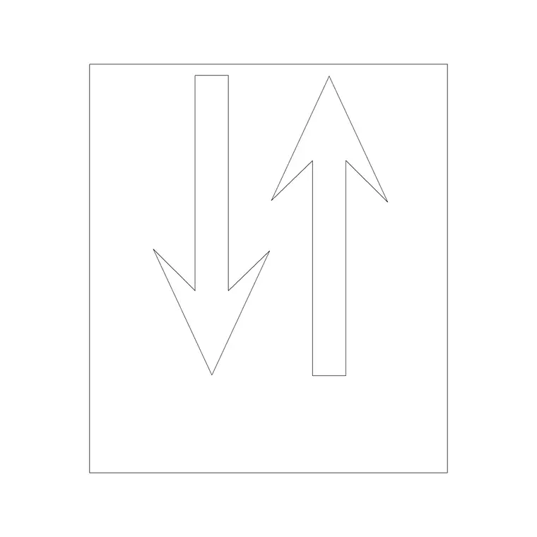
An arrow block is useful here for marking direction of travel along the route, especially at junctions where the accessible path diverges from the general circulation path, which happens more often than people expect, a main stair for general circulation with a separate ramp or lift route for the accessible path. Mark turning space at any point the route changes direction significantly, since a corridor can be wide enough for straight travel but still fail a turning circle requirement at a tight corner, and that's exactly the kind of thing a verification drawing is meant to catch before construction rather than after.
Turning space itself comes in two flavours worth distinguishing on the drawing, a full circular turning space and a narrower T-shaped turning space that works in a tighter corridor, and I annotate which type is being provided at each point rather than just drawing a generic circle and hoping it reads as compliant, because a T-shaped space that's slightly undersized in one leg is a completely different problem from a circular space that's a few centimetres short across the diameter, and the fix for each is different too. It's worth actually testing the turning space against furniture or fixed equipment that might later get placed nearby, a reception desk, a fire extinguisher cabinet, since a turning circle that's clear on the base architectural plan can quietly lose its required diameter once FF&E gets added in a later drawing phase that never gets cross checked back against the accessibility verification.
Slopes, thresholds, and the details that get missed
Ramps, thresholds, and any change in level along the route need their own callouts, slope ratios noted directly on the drawing rather than left to be assumed, and threshold height differences flagged even when they look trivial in section, because a 20mm lip that looks like nothing on a section drawing can still be a real obstruction at wheel height. This is the layer of detail that separates a verification drawing that actually verifies something from one that's just a floor plan with a few wheelchair symbols scattered on it for show.
One more thing I check along the route and it's easy to skip, wall mounted fixtures that protrude into the path, a wall lamp for instance, since many codes flag anything hanging into the route below a certain head height as a hazard for someone using a cane to navigate. Pull the fixture block onto the route drawing and confirm it's either mounted high enough to clear or set back outside the required clear width.
Presenting the verification clearly
Once the route, symbols, and clearances are all marked, keep the drawing's line weights doing the work, the accessible route line heavier than the general background plan, the wheelchair symbol and any clearance dimension in a colour that stands out on both screen and print. A verification drawing gets reviewed quickly, often by someone flipping through a stack of sheets, so the faster a reviewer can visually confirm the route is continuous and every clearance is called out, the faster it gets signed off.
I'll also add a short written route description alongside the drawing itself, entrance to lobby to corridor to restroom for instance, spelled out in plain text, because a reviewer scanning quickly benefits from being able to confirm the drawing matches a described sequence rather than having to trace a line through a busy plan unaided. It's a small addition that takes a few minutes and meaningfully speeds up how fast a verification drawing gets approved.
Further reading
Questions
Frequently asked
What symbols are essential on an accessible-route verification drawing?+
A wheelchair accessible symbol at the entrance, at every destination point, and at key decision points along the route, plus direction arrows at junctions where the accessible path diverges from general circulation.
Do exterior gates need to be checked on an accessible route drawing?+
Yes, if the accessible route passes through one. A gate block like an iron gate should be checked for clear opening width the same way an interior door would be, since many jurisdictions apply the same clearance logic to both.
Should slope and threshold details be shown on the plan or a separate section?+
Both if the drawing set allows it. Call out the slope ratio and threshold height directly on the plan at the location it occurs, and back it up with a section detail wherever the change in level is significant enough to need one.
Free downloads from this article

Free CAD block library
Download the blocks from this article — free, no signup